

- 10jaw member
- 13curved end
- 14knife edges
- 15knife edges
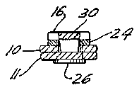
- 16lever member
- 17post
- 18opening
- 19curved end
- 20cross bar
- 21recess
- 22projection
- 24le
- 26rivet or eyelet
- 27openings
- 28openings
- 29opening
- 30projection
- 416lever member
- 568patent united states patents
- 775patent united states patents
Description
June 1l, 1963 w. E. BAssE'rT 3,093,147
NAIL CLIPPER Filed 0G11. 19. 1960 Mr-j my F/ 6` 5 INVENToR. VWM/AW E. 3,455,577
BY Mw? United States Patent 3,093,147 NAIL CLIPPER William iE. Bassett, N. Race Brook Road, Woodbridge, Conn. Filed Oct. 19, 1960, Ser. No. 63,660 Claims. (Cl. 132-755) This invention relates to a nail clipper for trimming finger nails, toe nails and the like.
This type of clipper comprises a pair of oppositely disposed cutting jaw members which are secured together at one end and have inwardly directed cutting edges at the other end which are normally biased into spaced relation and are moved into cutting relation by the manipulation of a lever member mounted for pivotal and swinging movement on the jaw members.
An object of the invention 'is to provide a nail clipper of said character provided with a nail tile and with means for maintaining the same in operative as Well as inoperative relation with reference to the jaw members. Nail clippers have been provided with nail files having prongs at the side edges thereof adapted to be engaged by the lever member for this purpose. However, such projections do not positively retain the le in longitudinal alignment with the jaw members since the projections permit of limited movement of hte tile about its pivotal connection with the jaw members. In order to overcome this objection, the present invention provides a construction which positively retains the file against sidewise movement in the inoperative position and in the operative or extended position in longitudinal alignment with the jaw members and which construction also retains the lever member against sidewise movement in the inoperative posi-tion thereof and necessitates the manual swinging of the lever member on its pivotal connection to free the file for movement to the operative or extended position.
Another object of the invention is to provide a nail clipper in which the lever member is provided with means which may be conveniently engaged by a thumb or finger and retained in position thereon during the camming of the jaw member to effect the trimming operation.
With the foregoing and other objects in view, reference is now made to the following specification and accompanying drawings in which the preferred embodiment of the invention is illustrated.
In the drawings:
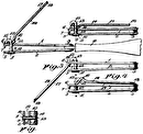
FIG. l is an enlarged plan view of a nail clipper constructed in accordance with the invention.
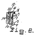
FIG. 2 is a longitudinal sectional view taken approximately on line 2-2 of FIG. l.
FIG. 3 is a view similar to FIG. 2 but showing the nail tile in operative position.
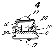
FIG. 4 is a sectional view taken approximately on line 4-4 of FIG. l.
FIG. 5 is a sectional view taken approximately on line 5-5 of FIG. 3.
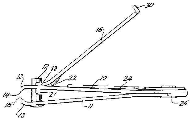
FIG. 6 is a side View of the nail clipper showing the parts in operative position for the cutting operation and with the nail file disposed in the inoperative position.
Referring to the drawings, the nail clipper illustrated therein may be used for trimming `finger nails, toe nails and the like and includes oppositely disposed cutter jaw members 10 and 11 which are secured together in any desired manner in superimposed relation at one end and which diverge therefrom in normally spaced relation to the remote end thereof. The normally spaced ends of the jaw members are curved inwardly as at 12 and 13 and are formed with concave knife edges yla and 15 adapted `to engage throughout :their length to effect a cut- "ice ting operation with the inward movement of the jaw member 10.
The jaw members may be stamped from sheet metal as separate parts and secured together as described or the same may be formed integrally and bent and secured in said superimposed relation. The said members are of spring material and are biased by the tension thereof against inward movement. In order to effect relative inward movement thereof, a levermember 16 is provided which is pivotally connected with a post 17 pivotally mounted on the jaw member 11 adjacent the curved end 13 thereof. The post 17 extends freely through an opening 18 in the jaw member 1t) with the protruding end thereof pivotally engaged by the lever member 16. This member is formed with a curved and bifurcated end 19 and with a cross bar 20 connected between the furcations thereof. The cross bar 2t) extends through a recess 21 in one side of the post 17' so as to pivotally connect the lever member thereto for swinging movement of the lever member from the inoperative position shown in FIGS. l, 2 and 3 to the operative position shown in FIG. 6 with the post rotated to dispose the recess 21 rearwardly.
It will be understood that when in the operative position shown in FIG. 6 of the drawings, the curved end 19 of the lever member is disposed against the jaw member x10 with the cross bar 20 positioned against the outer end of the recess 21. A projection 22 formed on the lever member adjacent the curved end 19 is disposed in engagement with the jaw member 10I as a fulcrum with the lever member arranged in angular relation with reference to said jaw member whereby swinging of the lever member toward the jaw member '10 will effect inward movement of the said jaw member and cutting action of the knife edges 14 and 15.
A nail tile 24 having le faces on each side is provided which is pivotally mounted in superimposed relation on the jaw member 10 by means of a rivet or eyelet 26 extending through aligned openings in the outer ends of the nail Ifile and jaw members with the ends of the eyelet flanged over for securing the :tile on the jaw member. By this arrange-ment the le is adapted to be disposed in the inoperative position between the lever 16 and the jaw member 10 as shown inVFIGS. 1, 2 and 4 of the drawings and to be swung about the eyelet as a pivot to the extended or operative position shown in FIG. 3 of the drawings.
In order to positively retain the le 24 in both the operative and inoperative positions against sidewise movement thereof, openings 27' and 28 are provided in the iile which are disposed in equally spaced relation on opposite sides of the eyelet 26. The jaw member 10E is also provided with an opening 29 which registers with the opening 27 when the le is in the inoperative position and which registers with the opening 28 when the tile is in the operative position. A projection 30 -on the free end of the lever f16 extending in right angular relation to the plane thereof is adapted to snugly it the openings 27 and 28' in the tile and the opening 29 in the jaw member 10. When the le is disposed in the inoperative position, the lever member 416 is biased by the outward tension of the jaw member 10 to maintain the projection 30 in the openings 27 and 29 and when the le is disposed in the operative position, the tension maintains the projection 30 in the openings 2S and 29, thus precluding any sidewise movement of the file when the same is disposed in the operative position for use for tiling or trimming nails and when in the inoperative position between the jaw member 10 and the lever member 16. It will be understood that the projection 30 is long enough to extend through 4both the registering 4openings in the le and jaw member 1G whereby the lever member is positively retained in the inoperative position shown in section in FIG. 2. This prevents relative sidewise movement of the lever member when the nail clipper is not in use. In order to free the lever member, the same must be raised to disengage the projection 30 from the aligned openings. The projection 30v also provides means by which the thumb or inger may be engaged against the outer end of the lever member so as to prevent slipping therefrom when camming the lever member downwardly for effecting a cutting operation.
In practice both the openings 27 and 28 and the opening for the rivet or eyelet 26 in the le 24 are made by a single tool. Accordingly, the openings 27 and 2S are connected with the opening for the rivet or eyelet by narrow slots but these slots are closed with the insertion of the rivet or eyelet. The opening 29 and the opening for the rivet or eyelet in the jaw member are made also by a single tool whereby these openings are connected by a narrow slot which is closed with the insertion of the rivet or eyelet. These slots serve no function other than facilitating the manufacture of the nail clipper.
While the preferred form of the invention has been shown and described herein, i-t is to be understood that the same is not so limited but shall cover and include any and all modifications of the invention which fall within the purview thereof.
What is claimed is:
1. In a nail clipper, oppositely disposed longitudinally extending members connected together at one end and having mating cutting jaws at the opposite end which are biased into normally spaced relation, a lever mounted on said longitudinally extending members for swinging movement toward said members and having means for forcing the jaw ends of said members together for effecting a cutting operation and said lever having an inoperative position in superposed relation with one of said longitudinally extending members, a iile member, means pivotally connecting said tile member on said one longitudinally extending member for movement from longitudinal superposed relation therewith to outwardly extended relation at one end of said one longitudinally extending member, said tile member having openings spaced longitudinally thereof and disposed on opposite sides of the pivotal connection of said le member with said one longitudinally extending member, said one longitudinally extending member having an opening disposed in alignment with one of the openings in said le member when said file is in said longitudinal relation and said opening in said one longitudinally extending member being disposed in alignment with the other opening in the iile member when the iile member is in sa-id extended relation, and said lever having an extension of a length and size and positioned so as to project into said one opening in said ijle member and into said opening in said longitudinally extending member when said openings are aligned with the le member disposed in said longitudinal superposed relation, and said extension being adapted to project into said other opening in said fiile member and into said opening in said longitudinally extending member when said openings are aligned with the file member disposed in said extended relation for retaining said iile member in said relations respectively against sidewise movement about its pivotal connection.
2. In a nail clipper as set forth in claim 1 in which said projection corresponds substantially in cross-sectional configuration to that of the openings in said tile member and the opening in said longitudinally extending member and snugly fits said openings wherein said file member is re- 4- tained against sidewise movement when in longitudinal relation with said one longitudinally extending member and when in outwardly extending relation therewith and said lever is retained against sidewise movement when in said inoperative position.
3. In a nail clipper as set forth in claim 1 in which the oppositely disposed longitudinally extending members consist of a single length of material arranged in doubled over relation medially of the length thereof and with the doubled over end disposed in superimposed relation.
4. In a nail clipper, oppositely disposed longitudinally extending members connected together at one end and having mating cutting jaws at the opposite end which are biased into normally spaced relation, a lever mounted on said longitudinally extending members for swinging movement toward said members and having means for forcing the jaw ends of said members together for etecting a cutting operation and said lever having an inoperative position in superposed relation with one of said longitudinally extending members, a le member, means pivotally connecting said tile member on said one longitudinally extending member for movement from longitudinally superposed relation therewith to outwardly extended relation at one end of said one longitudinally extending member, said tile member having an opening therethrough located adjacent the pivotal connection of said tile member with said one longitudinally extending member, said one longitudinally extending member having an opening therethrough located adjacent said pivotal connection of the le member therewith and which is disposed in registry with the opening in the le member when said file member is in said extended relation, and said lever having an extension of a length and size to project into said openings when said openings are in registry with the tile member disposed in said extended relation for retaining said tile member against sidewise movement about its pivotal connection.
5. In a nail clipper, oppositely disposed longitudinally extending members connected together at one end and having mating cutting jaws at the opposite end which have means normally biasing them to spaced relation, a lever pivotally mounted on said longitudinally extending members for swinging movement toward said members and having means for forcing the jaw ends of said members together for effecting a cutting operation and said y,lever having an inoperative position in superimposed relation with one of said longitudinally extending members, said one longitudinally extending member having an opening therein at the end thereof remote from the cutting jaw thereof, and said lever having an extension projecting outwardly in angular relation at the outer end of said lever and of a length and size to project into said opening when said lever is in said inoperative position for retaining said lever against side-wise movement, said lever having means to cause said biasing means to urge said extension into said opening, and said projection extending outwardly Iwhen said lever is in said operative position for engagement by a finger or the thumb of the user for facilitating Imovement of said lever member for effecting a cutting operation.
References Cited in the tile of this patent UNITED STATES PATENTS 775,568 LaMay Nov. 22, 1904 1,430,779 Winter Oct. 3, 1922 1,43 6,010 Carter et al Nov. 21. 1927-
