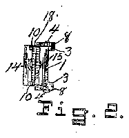
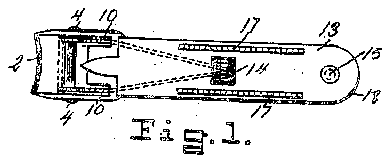
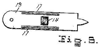

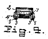
- 1plate
- 2cutting jaw
- 3lugs
- 4rivet
- 5hole
- 6plate
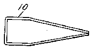
- 10spring
- 11holes
- 12arch
- 13top plate
- 14arch
- 16notches
- 17two serrated grooves
- 18semi circular groove
Description
Patented @et 3, 1922..
MNITEDSTATES PA-'MIENT vOFFICE..
FRANK WINTER, OF CHICAGO, ILLINOIS, ASSIGNOR TO MORTIMER LEVI'IAN, 0F MADISON, WISCONSIN.
NAIL GLIPPEBJ.
Application led December 1G, 1921. Serial No. 522,913.
To all 'Lo/1,0m t may concer/n:
Be it known that I, FimNK WINTER, a citizen ot t-he United States, residing at Chicago, in the county ot Cook and State of Illinois, have invented certain new and uset'ul Improvements in Nail Clippers, ot' which the following is a specification.
My invention relates to finger nail clippers or' practical and durable construction; and the objects ot my invention are, first, to construct a device with few parts, and positive action; second, to have certain elements adapted to more than one use; and third, to provide a spring loosely located within its bearings and not at any point subjected to severe strain, therefore of great durability.
I attain these objects by the mechanism shown in the accompanying drawings in which- F ig. 1, is a plan ot the complete device;
Fig. 2, is a rear elevation ot saine;
Fig. 3, is a plan ot the locking plate;
Fig. 4, is a front elevation ot the complete device;
Fig. 5, is a side elevation of same, open position shown by dotted lines;
Fig. 6, is a tront elevation of bottom plate;
Fig. 7, is a side elevation ot same;
Fig. 8, is a, bottom view of same;
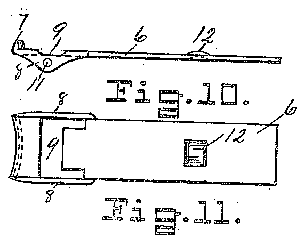
Fig. 9, is a Jfront lelevation ot lower jaw;
Fig. 10, is a side elevation of same;
Fig. 11, is a bottom view ot same;
Fig. 12, is a front elevation of the spring;
Fig. 13, is a plan ot' same;
Fig. 14, is a side elevation ot saine.
Similar numerals refer to similar' parts throughout the several views.
The bottom plate 1, is of sheet steel, bent downward across the front end and sharp ened Jforminga cutting jaw 2, thence ez tending` backward a distance, thence turned downward and backward into parallel alignment with the top portion and terminating in a halt round serrated end raised above the bottom line, lugs 3, extend forward and downward from the convex front end ot the plate and are drilled centrally to receive a rivet 4, a hole 5, is located concentric with the rounded rear end of same. An oscillating steel plate is provided of equal width with plate 1, and having the trent end turned upward and sharpened forming 7, which registers with the i aw a cutting Jaw 2, and passes inside ot the same, extending backward from the jaw 7, the plate 6, is turned downward on both sides forming flanges 8, and cut away between the flanges at 9, to allow the plate a tree movement in relation to plate l, and the spring 10, holes 11, are. located through the ,iianges 8 registering with the holes through the lugs 3, and adapted to receive the rivet 4, an arch 12, is formed a dist-ance from the rear end by forcing the metal upward, tor the double purpose ot' providing a seat for the rear ends of the spring l0, and also to provide a locking knob under the top plate 13, said top plate being provided with an arch 14, which registers with the arch 12, when the device is folded up and closed. Two serrated grooves 17, extend longitudinally of the top or locking plate adjacent the outer edges thereof, and the round rear end is concaved and registers with the rear end of plate 1, which is also concaved forming a semi circular groove 18, which is cross knurled providing a means Jfor rounding the edge of the `)finger nails, after being clipped with the cutting jaws. The locking plate is pivoted to the top of the rear end of plate 1, by a rivet 15.
As can be seen by-referring to Figs. 1-2 and 3, the iront end of the spring 10, is located under and to the rear of the cutting jaw 2, on plate 1, and the side members disposed in notches 16, then the plate 6, is slipped over the rear end and moved forward until the spring is engaged, then pressed downward until the holes 3 and 11, are in alignment and the rivet 4, inserted and secured, which will locate the rear'ends of the spring in the arch l2, and hold the cutting jaws 2 and 7 in proper working relation. The spring 10, is formed of spring wire bent backward and downward in two lines thence backward in parallel alignnient for a distance, thence converging to Contact at the rear ends. It is obvious that a spring so Jformed will be very unitorni as regards strains, and very durable.
Having thus described my invention, l claim:
In a device of the kind described, a plate with a cutting member formed on the troni. end, and bent downward and backward .a distance back of the cutting member, notches on each side to hold a spring, depending lugs integral with the plate directly below the notches drilled to receive a rivet, a second l0 provided with an arch adapted to lock over the top of the arch in the second plate, a serrated groove formed in the rounded rear ends of the lirst plate and cover plate, for rounding the edge of finger nails.
ln testimony whereof I aliX my signature 15 in the present of two subscribing Witnesses.
\ FRANK WINTER W'itnesses:
EDWIN D. LAWLER, LIDA OLSON.


