- 3bassett nail clipper mu 55 m wm w k 0 w
- 10members
- 11upper jaw member
- 12spot welding
- 13cutter jaws
- 14cutter jaws
- 15cutting or knife edges
- 16cutting or knife edges
- 17pin
- 18aligned openings
- 19aligned openings
- 20notch
- 22bar
- 23lever
- 24opening
- 25curved portion
- 26lug
- 28free end
- 30nail file
- 31file
- 32free end
- 34form securing flanges
- 35lugs
- 36lug or bump
- 37portion
- 40dimple or depression
- 41upstanding lug or projection
- 55bassett nail clipper mu
- 624now patent
- 664now patent
Description
March 20, 1956 w. E. BASSETT NAIL CLIPPER mu 55 m WM w k 0 w 3 any fi 2 a m 2 Mm 5 mu NE W m m m 5 73 W T- ATTORNEY United Span>tates Patent NAIL CLIPPER William E. Bassett, Woodbridge, Conn. Application June 16, 1953,=Serial No. 361,970
1 Claim. (Cl. 132-755) This invention relates to nail clippers and the like, particularly to that type of nail clippers in which a pair of flexible jaw members are secured together at one end and have cutting jaws at the other end normally held open by the resilience of the jaw members, and
the invention is especially intended as an improvement over the clipper shown in my Patent No. 2,477,782, granted August '2, 1949. This application is a continuation-in-part of my application Serial No. 172,077, filed July 5, 1950, now Patent 2,664,624, January 5, 1954.
In this form of clipper, a cam lever is operatively connected to the jaw members 'by having a cross bar on the end of the lever extend through an undercut slot in a pivot pin extending loosely through the jaw mem bers. The resilient pressure of the jaw members which causes them to normally spread apart also presses the cross bar into the undercut portion of the slot to retain the lever in operative position to manipulate the clipper. Such clippers usually have a nail file pivoted to the jaws, and the operating lever and file may have coacting means to hold the lever in place against turning. a
The principal object of the invention is to provide a nail clipper having a folding nail file movable from inoperative to operative position having an improved arrangement for retaining the file in inoperative position.
With the foregoing and other objects in view, I have devised the construction illustrated in the accompanying drawing forming .a part of this specification. It is, however, to be understood the invention is not limited to t-heispecific details of construction and arrangement shown, but may embody various changes and modifications within the scope of the invention.
In this drawing:
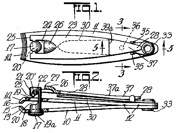
Fig. 1 is a plan view of a nail clipper illustrating one form of the invention;
Fig. 2 is a side elevation of the clipper shown in Fig. 1;
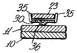
Fig. 3 is a transverse section on the line 33 of Fig. 1;
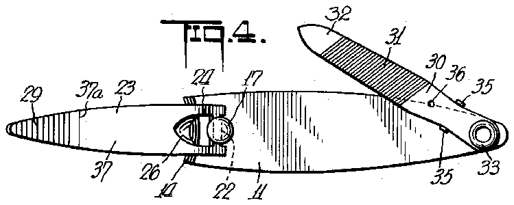
Fig. 4 is a view similar to Fig. l but showing the operating lever extended and illustrating a nail file attachment embodying one of the features of the invention;
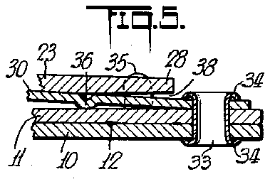
Fig. 5 is an enlarged, sectional view taken in the plane of the line 5-5 of Fig.1;
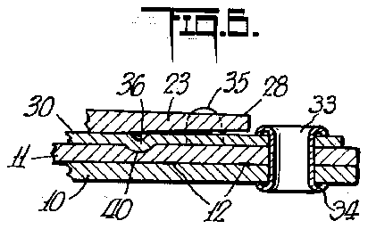
' Fig. 6 is a view similar to Fig. 5 but illustrating a modification; and
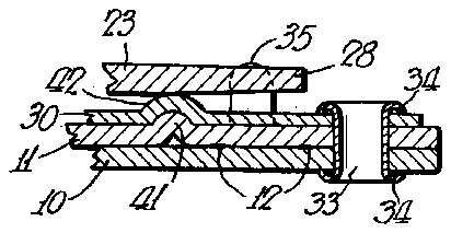
Fig. 7 is a view similar to Fig. 5 but illustrating a further modification.
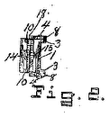
This improved clipper comprises two superimposed cutter jaw members 10 and 11 which are preferably stamped from sheet metal of fairly heavy gauge of any desired shape, but preferably of the substantially oblong shape shown, and which are secured in superimposed relation at one end portion by any suitable means, such, for example, as spot welding 12. These members are provided at their opposite ends with cutter jaws 13 and 14, the free edge portions of which are provided with cutting or knife edges 15 and 16 opposed to each other so that. when forced togetheron opposite sides of a finger- 2,738,795 Patented Mar. 20, 1956 nail, toenail, or the like, they will trim .it to the shape of these cutting edges, the free ends of the jaws being preferably ofiset from the members 1011 and inclined toward each other somewhat, as shown in Fig. 2, whereby those portions of the members 10-1-1 adjacent the jaws 1314 are spaced apart. These jaws 13-14 are normally held open, as shown in Fig. 2, and this may be done by various means, but preferably either one or both'of the members 10 and 11 are spring members, or made of resilient metal, which tend to assume this open position.
The means for operating these jaws and their cutting or knife edges comprises a pin 17 extending through aligned openings 18 and 19 in the jaws, with its head 19a on the under side of the lower jaw .and its shank extending through the upper jaw to a distance above this jaw, this shank being provided in one side with a curved transverse undercuit; recess or notch 20 opening through a side of the pin providing at its top an inverted curved hook portion 20 inwhich is seated a transverse bar 22 at the end of an operating lever 23. This bar is provided by cutting an opening 24 in this lever spaced a suitable distance back from the adjacent end, and this end of the lever is bentdownwardly as shown at 25 in Fig. 2, to restagainst the top of the upper jaw member 11, so that the spring action of the jaws will tend to swing the free end of the lever 23 downwardly against the top of the upper jaw member into the inoperative position, this action being secured by the lever action on the ends of the curved portion 25, and the bar 22 seating in the end of the notch 20 in the pivot pin. The leveris also provided with an upwardly pressed lug 26 a short distance from the pin 17, the end 27 of which when the lever is reversed may rest on the top of the upper jaw member 11 for operation of the cutter in the clipping operation. In moving this lever to this position, it is raised from the position of Figs. 1 and 2'about its pivot bar 22 to the position of Fig. 4 and then is swung in a circle about the pin 17, the pin during this movement turning in the jaws as a pivot for the lever to permit the lever to be swung to the operative position over the upper bar '11 in which position it 'is reversed or turned over from the position of Figs. land 2, so thatthe lug 2 6 is on the underside of the lever, and its freeedge 27 rests on the top of the upper jaw member 11, as will be understood, the bar 22 of the lever remaining in the undercut notch 20 of the pivot pin and forming a pivot for the lever. Now, by pressing downwardly the free end of the lever 23, the lug 26 will force the upper jaw member 11 downwardly or toward the other jaw member 10, and will force the cutting or knife edges 15 and 16 together for the clipping -or trimming operation. After use, the lever 23 may be swung again to the position of Fig. 4, using the pin 17 as a pivot, and then swung to the inoperative position on top of the jaw member 11 as shown in Figs. 1 and 2. If desired, the under side of the lever (which is the upper side when the lever is in the operative position), may be cut or roughened, as shown at 29, to form a better grip for the thumb when using the device. Also it is preferred that the end portion of this lever be bent slightly as shown at 37a, Fig. 2. This brings the portion 37 between this point and the free end 28 on a plane substantially parallel with the body of the clipper, when the lever is depressed into the position where the cutting edges grip and cut the nail, so that the thumb pressure'is exerting a force on the part 37 rather than on the sharp end of the lever. This bend also raises the free end 28 of the lever above the member 30 when in the folded position of Figs. 1 and 2 to provide a clearance under this free end, as
3 shown at 38, for insertion of a thumbnail to facilitate raising the lever.
Through the rear ends of the jaw members and 11 is formed an opening whereby the device may be connected to a key ring, chain or the like, and pivotally mounted at this end is a nail file 30. This is a flat blade member cut on either or both surfaces, to form the file 31, and it may be reduced in thickness and rounded or pointed at its free end 32 to provide a means for cleaning under the nail. The file is pivotally mounted on the upper side of the upper jaw member 11, as by means ofan eyelet 33 passing through openings in the members 10 and 11, and rolled over at its opposite ends to form securing flanges 34. This eyelet also passes through an opening in the file member 30 to form a pivotal mounting for this member to allow it to be swung in a plane substantially parallel to the plane of the members 10 and 11 to a folded position on the top of the upper member 11 when not in use, or to be swung laterally, as shown in Fig. 4, to a more exposed position for use. When in the position on the top of the member 11, as shown in Figs. 1 and 2, it lies under and is covered by the operating lever 23, so that it is protected and prevented from catching on clothing or other objects.
The lever 23 and file member 30 preferably have coacting means to hold the lever in place against lateral swinging. In the form shown, the opposite side edges of this file member adjacent the pivot 33 are provided with upwardly extending lugs 35 between which the free end portion of the lever 23 may seat and be held when in the closed or inoperative position of Figs. 1 and 2 and is prevented from being swung from this position when being carried or not in use. A lug or bump 36 on the under side of the nail file 30, which may be formed by punching through from the top side, or in any other way, frictionally engages the adjacent face of the upper jaw member 11 and is raised slightly against the spring action of the metal of the file to frictionally retain the file in the folded position, as shown in Fig. 3, so that the file is thus held against inadvertent movement laterally out of its closed position but can be readily swung to the operative extended position for use. The frictional retaining lug 36 on the nail file 30 provides the necessary friction for holding the file in folded position without in any way affecting the simplicity of manufacture or case of assembly of the clipper parts. The frictionally held file 30. through the lugs 35, holds the lever 23 against sidewise swinging.
In the form shown in Fig. 6, the upper jaw member 11 is provided with a dimple or depression 40 to receive the lug or bump 36 on the file and thus hold the file 30 more securely than when friction alone is relied upon as n the form shown in Figs. 1 to 5.
In the form shown in Fig. 7, the upper jaw member 11 is provided with an upstanding lug or projection 41 to be received in a hole, dimple or depression in the file member 30 so that the file is held quite securely against swinging, as in the form shown in Fig. 6.
It should be noted that the holes, dimples and lugs are such that the file may be manually swung to operative or inoperative positions without undue effort, but the file is not likely to be swung out of position, accidentally. It will be clear that the more firmly the file is held, the more firmly will the lever 23 be held against accidental swinging.
It should also be understood that if no nail file is provided, the top jaw member and operating lever could be provided with the cooperating projections and dimples the same as those on the jaw member and file, to prevent accidental swinging of the lever on the jaw.
While the invention has been described in considerable detail and preferred forms illustrated or described, it is to be understood that various changes and modifications could be made within the scope of the invention as defined in the appended claim.
I claim:
In a nail clipper, a pair of relatively resiliently movable jaw members connected together at one end and having offset cutting jaws at the other ends, means including a jaw operating lever for moving said jaws for cutting, said lever being pivoted for lateral swinging about a pivot adjacent said cutting jaws, said lever when in inoperative position being positioned along one of said jaw members, a nail file member pivoted to said jaw members for lateral swinging movement, the pivotal axes of said operating lever and nail file member being substantially parallel, said nail file member and adjacent jaw having cooperating lateral abutment means to resist lateral swinging of said file member on its 21djacent jaw and said lever and file member having abutment means to resist relative lateral swinging movement.
References Cited in the file of this patent UNITED STATES PATENTS
