
- 2aug
- 3file
- 11'upper jaw'member
- 22urved l'portion 25,1ar'idthe bar
- 23lever
- 28free end
- 30le
- 31portion
- 32free end
- 34form securing flanges
- 35lugs
Description
Aug 2, 1949. w. E. BASSE-r1 2,477,782
NAILl CLIPPER Filed Feb. e, 1947 Patented Aug. 2, v1949 `UN1TE IQF1"`IH? l v :Ja-477,782' Y f I.
cLnaontv William .n.nassett, Woodbridge, Gann. nmilieatidn February 6, 1947, k:serian @m7262785 fascism. (ci. isa-e755) mails, ntoe inairls, and v.the dike,- particularly thefit'ype of =cl1ipper compris`ing a a'pair lof `curved cutting jaws normally fhel'd 'in `spaced relation, withiafpivotedleverifor lfo'rc'ing the jawstog-ether for itheiclipping operation, :andlhas for anfc'bject .to :provide .such a device with an improved form 'of inalle which maybeswung outwardly for -use and whenfnot 'in use 'is .covered and protectecl. Anothersobject "is itc fpr'ovidef'means on kthis file for holding :the J:operating lever of the clippers in Ihheiinonerativeapositionwhen not iii-use. Y the rioregoing and fother objects `'in view, iihave televised 'thexconstruction Aillustrated :in the accompanying drawing *forming ia lpart of *this specification. tis,however,itebeunderstoo'dfthe invention is not limited to the 1-speoiic `'details -of construction and arrangement shown, Abut may embodyvarious changes and fmodicaticnswithin the scope of .the invention. f
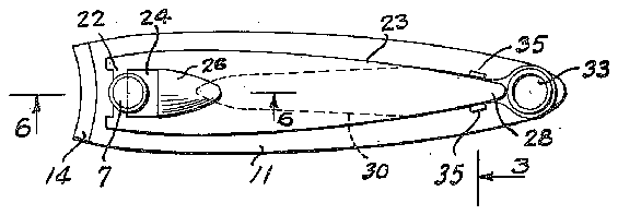
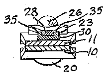
'.In this-drawing: Eig. iris a 'top plan view of fthe device'on -an enlarged scale, vv's'locliwing `it fin a closed `or lix'ioper'ative condition;
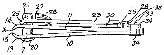
' @Eiglis afside view; y 31iis '-aflsection substantially -on iline ofliilifg. il;
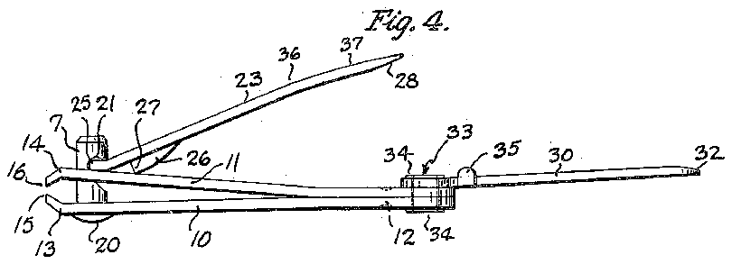
Fig; s is 4a t'op plan view showing the'operating lever swung :up from ltne normal or'incperative position; v f
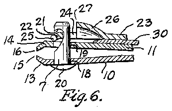
I5 'is ra iside View lshowing ithe cutting jaw operating mechanism in fthe roperative position 1and .showing `the fiile .swung out to fone position of use, .and l6y is ia detail section lsubstantial-h? Jon line -6rofiElig. il.
This improved :clipper coin-prisesv two superino'- posed cutter g'aw members -Ii and -I I which are' preferably-stamped if-rom sheet metal of fairly heavy gauge of any desired shape, but preferably of the substantially roblong shape shown, and which are .secured ,fin the :superimposed :relation atv one end portion by any suitable means, such, for example, as spot welding I2. These members are provided lat ytheir opposite 'ends with cutter jawsl and I4, the free edge portions of which areypnovided withA curved vcutting .or kriiieiedges Illifand I6 .opposed to eachfotherso that vfv'vtnain forced together on opposite sides of a nger nail, toenail, or the like, they will trim it to the curved shape of these cutting edges, the free ends of the jaws being preferably inclined toward each other somewhat, as shown in lFigs. 2, 5 and 6. These jaws are normally held in separated or spaced relation, as shown in Figs. 2, 5 and 6, and this may 55 be done by various means, but pre'erallyther fone for iboth fof lthemmbers LIIl 'and YII -aiifesp'ring members, primado of resilient ine-tal, vwhich tend rtdassumethi'sfpositin. I
. FI-he fmeans lfor operating ftheseij'aws ah'dftheir Acutting :or Rknife edges k1'c'(impr-isos fa pin or 'rivet fl iex'tending through Aaligned "openings 1158 and in the fjaws, 4`with its -head l20 ion thelu'nde'r side of fthe 'lower jaw 'andits-s'hank extending through the iupper jaw 'to afdistan'celabove this jaw, lthis. shank "bei-ng lprovlide'd one side with -fa curved ytransverse recess or fiiotch vproviding at its top `an linvert-fed curved hook portion l2-'I in Awhich iis seated fa transverse ba-T7212 at ythe xend dfi'a'n voperating le-vo'r 23. f This "bar is :provided ybytvziittf';ihg ein iopening '24 in this y-lfeve'r 'spaiced a suitale tance yback from `.itsl ffree "end, and the free rend jof the lever lis bent-downwardly, as shown fat 25, *tf' rest against the topo'f 'the nppierfjawlmember FI, so that lthe spring :action of -the Ajaws'will tend to swlingfthe free Jend of vthe level' 23 downwardly against fthe 'top of the upper aw jm'ember out "f the way into thev inoperative position, 'as 'shown inlliligs. V1 and'2;tliisaction vbeing secured by the lever action jon the Aends di i'the Icurved l'portion 25,1ar'idthe bar 22 lseating in the hook IZI o'fthe notch in the rivet. Thelever is alsoprdvidedwith 'an-.upwardly pressed'lug '26 a short'distance 'from the rivet or ilpin 1, `the Ai".1"ee-^end'2"I nii which, when the lever is reversed, Vmay vrest Von `the vtop 'of the upper j aw Amember -I 4I for operati-on of fthe 'cutter in 'the :clipping operation, this position l'being 'shown in Fig. 5. {In movi-ng ithis /deviceto 'this 'posi-tion the lever is 'raised ffromthe position of Figs. Al and 2 about iits piivot bar '22 to the position o'f iFig. 4, and then is @swung in 'a circle about the pin flfthe pin during this Imovement tui'n'ingin the jaws' I'as a pivot for the lever to peri'ni'tjthe lever 'to be -swfung 'to the lposition 'of Fig. 5,"i'n whichiposition it iis reversedor turned ovei'frorn the posi'ti'on o`f Figs. v1 and 2'so that `"the Vlu'gffl S-on ithe undersidof the1ver,'and"i'bsfree edge 2F! Irests `ron the top fo'f the 'upper jaw'member 11 as shown iin Fig. lthe bar Y22 'of "the lever "re-V maining the notch 2-I "of the v'pin and vf rm'i'ng a pivot 'for the iever. Ncw, -by pressing dwnf wardly the free end 'of the lever 23," the lug 2li will I'forceftheupper liaw member iI'I downwardly or toward the other jaw member II), and will force the cutting or knife edges I5 and I6 together for the clipping or trimming operation. After use, the lever 23 may be swung again to the position of Fig. 4, using the pin 1 as a pivot, and then swung to the inoperative position on top of the jaw member II as shown in Figs. 1 and 2. It
desired, the free end 28 of this lever may be tapered and rounded and reduced in thickness to provide a means for cleaning under the linger nail, and on its underside (which is the upper side when the lever is in the position of Figure 5) it may be cut or roughened, as shown at 29, to form a better grip for the thumb when using the device. Also it is preferred that the end portion of this lever be bent downward as shown at 36, Figure 5. This brings the portion 31 between this point and the free end 28 on a plane substantially parallel with the body of the clipper, particularly when the lever is depressed into the position where the cutting edges grip and cut the nail, so that the thumb pressure is exerting a force on the pad rather than on the end of the lever. This bend also raises the free end 28 of the lever above the member 30 when in the folded position of Figure 2 to in the inoperative position, and that this le in turn is provided with means for holding the lever against inadvertent movement laterally out of its closed position on the upper side of the upper jaw member, but that the lever may be readily swung to its operative position and the file may be readily exposed and swung to a position for use. The lugs 35 on the le are preferably located relatively close to the pivotal mounting for the le, and also the free end of the operating lever, so' that they will have the maximum holding eiect on the lever and will effectively prevent its being swung laterally out of its closed position on provide a clearance under this free end as shown at 38 for insertion of a thumb nail to facilitate raising the lever.
Through the opposite ends of the jaw members I0 yand Il is formed an opening whereby the device may be connected to a key ring, chain or the like, and pivotally mounted at this end is a nail le 30. This is a flat blade member c ut on either surface, preferably the upper surface, to form the file 3|, and it may be reduced in thickness and rounded at its free end 32 to provide a means for cleaning under the nail. It is pivotally mounted "on the upper side of the upper jaw member I l by means of an eyelet 33 passing through the opening in the members lll and ll and rolled over at its opposite ends to form securing flanges 34.
,This eyelet also passes through an opening in the member to form a pivotal mounting for this member to allow it to be swung in a, plane substantially parallel to the plane of the members I0 and l l to a position on the top of the upper member II when not in use, or to be swung laterally, as shown in dotted lines Fig. 4, to a more exposed position for use than when lying over the upper member Il. When in the position on the top of the member ll, as shown in Figs. 1 and 2, it lies under and is coveredl by the operating lever 23, so that it is protected andv prevented from catching on clothing or Other objects. y
On the opposite side edges of this le member ladjacent `its pivot 33, it is provided with a, pair of upwardly extending lugs 35 between which the free end portion of the lever may seat and be held when in the closed or inoperative position of Figs. 1 and 2, and .prevent its inadvertently being swung from this position when carrying or not in use. The pivotal mounting for the le 30 is a fairly tight friction mounting so it is not loose to swing freely about the pivot, but it is tight enough for a frictional pivot so that the le is frictionally held in any position to which it may be swung, but still may be swung-to any of these positions by the operator, as desired. By using a ,tubular eyelet for the pivot mounting of the le, the opening through the end of the device for mounting it on a key-ring or chain is maintained.
It will be seen from the above that this novel construction and arrangement comprises a nail file and cleaning element which is normally covered or enclosed by the operating lever when the top of the le member during the carrying ioperation.
Having thus set forth the nature of my invention, what I claim is:
1. A nail clipper of the character described 'comprising connected members having cutting jaws at one end normally held apart, a pivotally mounted operating lever for forcing the jaws to- 'getherfor the clipping operation and arranged to lie adjacent the outer surface of one ofthe membersl when in inoperative position, a le member pivoted to said latter member adjacent its other end to swing in a plane parallel to said member to and from a position on the outer side of .said member under the lever, and said le member being provided with laterally spaced ,lugs arrangedto receive the lever between them to hold it against lateral swinging movement.
2. A nail clipper of the character described l, comprising connected members having cutting jaws at one end normally held apart, a pivotally mounted operating lever for forcing the jaws together for the clipping operation and arranged to lie adjacent the outer surface of one of the members when in inoperative position, a fue member pivoted to said latter member adjacent the other end thereof to swing to and from a position on the outer side of said member, and means on the le member to hold the lever against lateral swingling movements parallel to the plane of said member when it is in said inoperative position.
3. A nail clipper of the character described comprising connected members having cutting jaws at one end normally held apart, a pivotally mounted operating lever for forcing the jaws together for the clipping operation and arranged to lie adjacent the top surface of the upper memper whenin inoperative position, said lever being adapted toswing laterally, a le member pivotally 'connectedto the other end portion of said upper member to swing in a plane parallel to said member to and from a position on the upper side of rsaid member, and laterally spaced lugs on the ille {member between vwhich the lever seats to hold it against lateral swinging movements.
Y WILLIAM E. BASSETT.
REFERENCES CITED The following referenlces are of record in the fileof this patent:
Seymoure A Dec. 15, 1931


