- 1h a- seymoure
- 2 l fi
- 5 fi
- 11members
- 12end
- 13portions
- 14portions
- 15other portions
- 16portion
- 17form coacting cutters
- 18form coacting cutters
- 20swivel bolt
- 22notch
- 23lever
- 24fiat bar
- 25flanges
- 26cam
- 27bolt aperture
- 28cross bar
- 29end recess
- 31ribs
- 32ribs
- 33depressions
- 34depressions
- 36ridges
- 90- fingeb nail clip application tiled lay
- 557h a- seymoure
- 836h a- seymoure
Description
Dec. 15, 1931. H A- SEYMOURE 1,836,557
FINGER NAIL CLIP Filed May 2o, 1929 INVENTOR lghraeelAgunawvv BYH ATTORNEY operation which forme Patented Dec. l5, 1931 HORACE A. SEYIOUBE. 0F
IOUBE, INCORPORATED, NECTICUT NORWALK, CONNECTICUT, ASBIGNOR TO HORAGE A.. SEY- OF NORWALK CONNECTICUT, A CORPORATION 0F CON- FINGEB NAIL CLIP Application tiled lay 90, 1929. Serial No. 364,886.
The invention relates in general to a. manicuring im lement of the t pe 1n which two resilient b ades are secure together at one end and have inturned cutters at .the other end and which cutters are moved into operative engagement by means o f a. cam actuating lever secured to a swlvel bolt passed through apertures adjacent the cutter forming ends of the resilient members..
In such devices as heretofore known 1t was a usual construction to secure the actuating cam lever to the swivel bolt either by means of a pin form of pivot or the actuating lever was secured in place by means of a pm and slot connection. These prior constructlons possessed several inherent disadvantages, the pivot pin form of mounting being difficult to assemble as a cheap factory proposition and the pin and slot form of construction having the disadvantage of permltting an accidental demounting of the assembled parts whensubjected to careless or rough usage.
Accordingly, the primary object of the invention is to provide a simple form of manicure implement of the type above outlined, and which features a simplified form of connection between the swivel bolt and the operatin `cam lever, so as to permit the marketing o such an article at an extremely low price. f
Broadly, this object of the invention is attained by providing the component parts. as simple one-piece pressings and in providlng the swivel bolt with an undercut notch designed to permit the ready insertion therein of a pivoting cross bar formed on the o erating cam lever at the time it was punc ed to shape.
Another object of the invention is to pro-y vide in connection with the operating cam lever element of the combination, a form of nail file which will resent a slightly concaved filing surface, esigned to conform, at least roughly, to the configuration of the end 'of the finger-nail, and which at the same time can be formed as a art of the stamping d) the operating cam lever, and without necessity of machining the part to provide the requisite concaved filing surface.
This object of the invention is attained by forming on one side of a flat portion of the operating lever a pair of parallel ribs and a series of file ridges disposed between the ribs in such way that the ribs and file `ridged surface form in effect a concave surface.
Various other objects and advantages of the invention will be in part obvious from an inspection of the accompanying drawing and in part will be more fully set forth in the following particular description of one form of mechanism embodyin my invention, and the invention also conslsts in certain new and novel features of construction and combination of parts hereinafter set forth and claimed.
In the accompanying drawings:
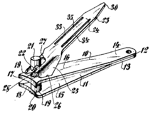
Fig. 1 is a view 1n perspective of a mani curin implement constituting a preferred embo iment of the invention;
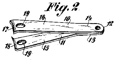
l Fi 2 is a perspective view of the resilient mem ers shown in Fig. 1 with the operating lever and swivel bolt removed; o
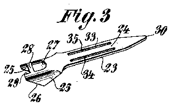
Fig. 3 is a similar view of the operating cam lever;
Fig. 4 is a view of the swivel bolt;
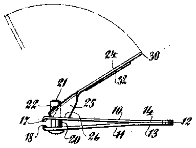
Fi 5 is a view in side elevation showing in fu l lines the cam lever in operative position'to actuate the cutters, and showing in dotted line the position of the camlever in its movement into position to be' folded against the adjacent resilient member;
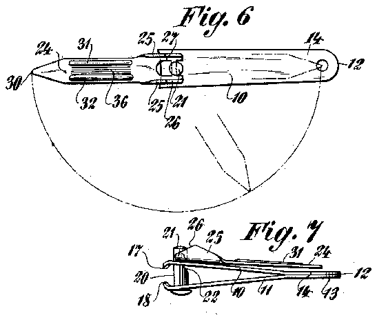
Fig. 6 is a plan view showing in full lines the position of the cam lever whenswung from the dot and dash positions 'into the distended osition prior to being turned over into t e position shown in Figs.'1 and 5; and
Fig. 7 is a showing in side elevation of the cam lever folded into its out of the way inoperative position.
In the several drawings there is shown two resilient members 10 and 11 superposed and welded to ether at one end 12. Portions 13 and 14 a jacent said end 12 lie in contact with each other and other portions 15 and 16 extend from the contactmg portions divergently of each other and have their free ends inturned towards each other to form coacting cutters 17 and 18. Each of the members l5 and 16 is provided with an aperture 19 in axial alignment. A swivel bolt 20 is rotatably mounted in the aligned apertures 19 and is provided adjacent its upper end 2l with a transversely extending and undercut notch 22 cut inwardly and upwardly from one side of the bolt 20. This notch is disposed opposite the portion 16 when theresilient members are in their normal position as shown in Fig. 7.
The cutters are moved into their cutting position against the resiliency of the mem` bers 10 and 11 by means of an operating cam lever 23, more particularly shown in Fig. 3. The cam lever is an integral pressing and comprises largely a fiat bar 24, the opposite edges at one end provided with a pair of 1ntegral flanges 25. The forward edges of these flanges are beveled as shown at 26 to form cams adapted to bear on the portion 16 of the resilient member 10 and coacting with the swivel bolt 20 to cause the cutters to approach each other. The portion of the lever 23 between the flanges 25 is recessed to provide a bolt aperture 27 and the forward side of this aperture is outlined by a cross bar 28, and in advance of the cross bar the adjacent edge of the lever is provided with an end recess 29.
The free end of the operating cam lever is pointed and somewhat flattened as shown at 30 to form a nail cleaner.
During the process of forming the operating cam lever the flat surface 28 is subjected to a die pressing operation which forms a pair of parallel rounded top ribs 31 and 32 on one side of the blade, an there is similarly formed on the reverse side a pair of slotted depressions 33 and 34. The depressions 33 and 34 are provided with a series' of transversely extending file ridges 3 5 which form long, narrow file surfaces des1gned to engage the fingernail in filing thesame across the top of the nail and in a directionsubstantially parallel to the plane of the na1l.
Between the ribs 31 and 32 on the reverse side of the lever are a series of tiling ridges 36 extending parallel to and disposed between the ribs 31 and 32. lVliile it is true that the portion of the blade provided with the le ridges 36 is substantially flat, the effect of the upstanding rounded top ribs at opposite sides of the filing surface is to form in eii'ect a concaved filing surface designed to conform, at least somewhat roughly, to the configuration of the ends of the fingernails. This construction is designed to permit a ling of the nail while the blade extends substantially perpendicular to the plane of the nail.
This disclosure features a construction which is designed to economize in manufacturing costs so as to produce an article which can be marketed cheaply. The resilient members as well as the operating lever are simply pressings, and the conventional swivel bolt may be easily provided with the peculiar' hook shaped notch disclosed in Fig. 4. The resilient members l0 and ll are easily welded together at their contacting ends to form the unit shown in Fig. 2. ln assembling the cam operating lever in position it is simply necessary for the assembler to pass the swivel bolt upwardly through the apertures and by manually depressing the resilient members towards the closed portion as shown in Fig. 5 the lever may be positioned in place first by disposing it in the position shown in dotted lines in Fig. 5 and then shoving it towards the end 12 until the cross bar 28 engages in the open end oi' the notch 22. Releasingr the holding pressure on the resilient members permits the portion 16 to react on the level' forcing the cross bar upwardly as shown in Fig. 5 and until the cross bar engages the upper closed end of the notch in which position it is held by the resiliency of the two members 10 and 11 acting through the swivel bolt. It is apparent from this construction that the cani lever may be disposed in the operative position shown in Figs. 1 and 5 and in which case the cam 26 is in operative position bearing on the adjacent face of the resilient member 10. Pressing downwardly on the free end ofthe cam lever will cause the cam to rock about its high point and in its effort to elevate the swivel bolt the eutters will be brought into cutting relation. Releasing pressure on the actuating lever permits the cutters to be restored to their normal open position -due to the resiliency of the members of which they form a part. The operating cam can be swung about the swivel bolt and into the position shown in Fig. 7 where the cam lever rests fiat against the adjacent resilient member with the cam forming flanges projecting outwardly therefrom and serving to protect the end of the swivel bolt as shown in Fig. 7.
I claim:
1. In a nail clipper, a one-piece stamping one portion of which is substantially flat, one side of said portion provided in spaced relation to its longitudinal edges with a pair of die-pressed parallel rounded top ribs extending longitudinally of the blade, the portion of the side between the ribs provided with file ridges and coacting with the ribs to form a nail file somewhat concaved in transverse section.
2. A nail clipper comprising a long one piece flat stamping including a substantially flat portion provided on one face with a pair of parallel file slots in spaced relation to the edges of the pressing, a pair of round top ribs projecting from the opposite face of the pressing and opposed to the file slots in the first named face and file ridges disposed between said ribs and in the file slots. l
3. A nail clipper 'comprising a one piece lever including a substantially ilat portion provided at one end with means adapted to coact with other means for mounting the vsaine in place, a pair of parallel file slots in one side of said blade, and a pair of ribs projecting from the opposite side and opl, posed to the file slots.
Signed at New York, in the county of New York and State of New York, this 7th day of May, A. D. 1929.
HORACE A. SEYMOURE.


