

- 3terminal end
- 10members
- 12members
- 14connected ends
- 16jaws
- 18jaws
- 20lever
- 22stud
- 24bifurcated end
- 26fulcrum point
- 28terminal end
- 30elements
- 32elements
- 34hollow rivet
- 36washer
- 40notch
- 66washer
- 80swung
- 83patent united states patents
- 768patent united states patents
Description
Sept. 12, 1961 M. E. HERSTEDT 2,999,505
COMBINATION NAIL CLIPPER AND TWEEZERS Filed Nov. 23, 1959 30 I4 INVENTOR. M. E. HERSTEDT 38 3s FIG. 6 34 FIG 7 ATTORNEY 2,999,505 COMBINATION NAIL CLIPPER AND TWEEZERS Martin E. Herstedt, 208 15th Ave., East Moline, Ill. Filed Nov. 23, 1959, Ser. No. 854,825 1 Claim. (01. 132-735 This invention relates to a combination tool and more particularly to a combined nail clipper and tweezers.
The principal object of the invention is to provide an improved combination tool or implement of the character described, utilizing, as a typical nail clipper, the combination of a pair of tweezer elements which are designed to occupy a storage position which will not interfere with the normal operation of the tweezers and to occupy an operative position which combines the function of the tweezers with the nail clipper to make the tool more convenient and useful. It is a principal object of the invention to provide a design that may be economically constructed and sold at a relatively low cost. The overall structure, when both the tweezer elements and the nail clipper operating lever are in storage or folded positions, is relatively small and may be conveniently carried in purse or pocket.
The foregoing and other important objects and desirable features inherent in and encompassed by the invention will become apparent to those skilled in the art as a preferred embodiment of the invention is disclosed, by way of example, in the ensuing specification and accompanying sheet of drawings, the several figures of which are described below.
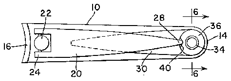
FIGURE 1 is a plan of the tool with all elements in folded or storage positions.
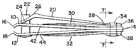
FIGURE 2 is an elevation of the same.
FIGURE 3 is a plan of the tool with the tweezer elements extended or in operating position.
FIGURE 4 is an elevation of the same.
FIGURE 5 is a view showing the tweezer elements manually compressed, as in use.
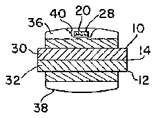
FIGURE 6 is an enlarged sectional view as seen along the line 6-6 of FIGURE 1.
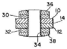
FIGURE 7 is an enlarged sectional View as seen along the line 7-7 of FIGURE 2.
Those familiar with the art will recognize in the drawings that the nail clipper is of typical construction, comprising a pair of complementary members 10 and 12 arranged in juxtaposed position and having one pair of ends rigidly interconnected as at 14. The manner of interconnection is commonly accomplished by spot Welding or the like; although, this detail is largely immaterial. The members 10 and 12 are constructed of steel and are designed and arranged so as to possess an inherent bias which normally keeps their opposite ends apart, as shown in FIGURES 2 and 4. These opposite ends are provided respectively as complementary cutting jaws 16 and 18, which, when closed or moved together, operate to occlude to clip nails as of the fingers of the user. The manner of causing the jaws to open and close involves the use of a lever 20 shaped and mounted in such manner as to be swingable from a folded or storage position as shown, to an operating position, which is not illustrated in detail, because it should be familiar to those versed in the art. Fundamentally, the mounting of the lever 20 includes at the jaw-proximate end thereof a stud 22 which passes through alined apertures of the jaws or members on an axis normal to the general planes of these members. The stud is headed at one end to engage one of the members and projects beyond the opposite members, having therein a notch which receives the bifurcated end 24 of the lever. In operation, the lever 20 is swung 80 from its position as shown, about the axis of the stud 22, and then is swung another 180 about a transverse axis afforded by a connection between the bifurcated end 24 and ice 2 the notched end of the stud 22. In the latter position, a fulcrum point 26 on the lever engages the outer surface of the member 10 and manual pressure on the lever 20 will cause the jaws 16 and 18 to come together. Release of manual pressure causes the jaws to open, because of the inherent bias in the members 10 and 12.
The foregoing describes a nail clipper of typical construction. As shown in FIGURES 1 and 2, particularly, the lever 20, when occupying a storage position, overlies the member 10, and has its free or terminal end '28 proximate to the connected ends 14 of the members. The shape of the lever 20 is such that it is closely outwardly spaced from the outer surface of the member (FIGURES 2 and 4).
The improvement provided according to the present invention comprises a pair of tweezer elements 30 and 32 mounted on the connected ends 14 of the members by pivot means preferably including a hollow rivet 34 and upper and lower washers 36 and 38. If desired, the washer 36 could be provided as an integral part of the tweezer element 30, and the same applies to the washer 38 relative to the tweezer element 32. The connection effected by the hollow rivet is such that the two tweezer elements 30 and 32 are rigidly interconnected so that they turn together about the axis of the hollow rivet 34, which, of course, is parallel to the axis of the lever-mounting shaft 22. Thus, the two elements 30 and 32 are free to turn in unison about the axis of the hollow rivet 34 and are capable of occupying a storage position as shown in FIGURES 1 and 2 or an operating position as shown in FIGURES 3, 4 and 5. In the storage position, the elements 30 and 32 lie respectively closely along the surfaces of the clipper members 10 and 12, and, particularly, the element 30 occupies the space between the inner surface of the folded lever 20 and the outer surface of the proximate clipper member 10. The other member 32 lies closely outwardly alongside the other clipper member 12.
For the purpose of providing an interlock between the upper tweezer element 30 and the lever 20, the upper washer 36, or the upper portion of the element if the washer 36 is regarded as an integral part of the element, is provided with means for releasably receiving the free or terminal end 28 of the lever. This means in the present case comprises a notch 40 in the washer 66, or its equivalent, so arranged that when the parts are in the FIGURE 1 position, the terminal end 28 of the lever 20 is received in the notch. As best shown in FIGURE 7, the notch 40 is so shaped as to enable ready release and receipt of the lever end 28.
When the tweezer elements 30 and 32 are extended in their operating position (FIGURE 4), they may be manually squeezed together to the position of FIGURE 5. The elements are of steel and possess inherent bias so that they normally occupy the position of FIGURE 4.
Since the elements 30 and 32 are of relatively thin cross section, they do not materially add to the size and weight of the overall tool. Cooperative portions of the elements may be designed so that they frictionally cooperate With the outer surfaces of the clipper elements 10 and 12. For example, the spacing between the free or terminal ends of the elements may be such that when they are in their storage position they frictionally engage portions of the members 10 and 12, as at 42 and 44. See FIGURE 2. Or, if desired, the frictional characteristic may be accomplished at the connected end 14 of the members by means of a tight frictional fit between the inner surfaces of the members and elements as the hollow rivet 34 is ailixed. In either event, the frictional association between the elements 30 and 32 and members 10 and 12 retains the elements in storage position against all expected forces. At the same time, when the elements are stored, the notch 40, cooperating with the terminal end 3 28 of the lever 20, maintains the lever 28 in folded or stored position against all expected forces.
As previously set forth, the combination tool increases the convenience and usefulnes of the conventional nail clipper. The tweezers are a handy item or complement to the tool, since the two are often used together. The cooperative relationship between the combined structures when in storage and operating positions will be evident. Features and advantages, other than those categorically enumerated, will readily occur to those versed in the art, as will many modifications and alterations in the preferred embodiment illustrated, all of which may be recognized by those versed in the art, all without departure from the spirit and scope of the invention.
What is claimed is:
A combination nail clipper and tweezers, comprising: a pair of complementary members fixedly connected together at one pair of ends and normally biased apart at their opposite pair of ends, said opposite ends having cooperative jaws; means at said jaw ends for effecting closing and opening of the jaws and including a lever pivoted to the members at said jaw ends on an axis normal to the members for optional swinging about said axis to a folded position in which said lever lies along and in closely spaced relation to the outer surface of one member and having a terminal end adjacent to said connected ends of the members; pivot means at, said connected ends and beyond said terminal end of the lever and including a shaft 2,999,505 I v. U r
turnable in said connected ends on a second axis parallel to the lever axis and having opposite end portions pro jecting outwardly respectively beyond the outer surfaces of said members; a pair of tweezer elements fixedly connected to and carried by said opposite end portions, respectively, at the outer surfaces of said members for selective swinging about said pivot means axis between an operating position extending away from the members to a storage position in which said elements lie respectively closely along the outer surfaces of said members with one element lying between said one member and the folded lever, said elements being of such length that the free end of said one element lies short of the lever pivot in its storage position, said elements in their operative position being biased apart to enable manual squeezing thereof to bring their free ends toegther; and head means fixed on the one end portion of the shaft at the same surface as the lever and said head means and the terminal end of the lever having cooperating parts operative in the storage position of said elements and the folded position of the lever to releasably retain said respective positions of said elements and lever.
References Cited in the file of this patent UNITED STATES PATENTS 768,083 Sickles Aug. 23, 1904 1,046,361 Wolff Dec. 3, 1912 2,738,795 Bassett Mar. 20, 1956


