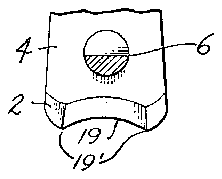
- 1jaw
- 4arms
- 5rivet
- 6pin
- 8lever
- 9notch
- 11bent portion
- 12cutting edges
- 13cutting edges
- 14cutting edges
- 15cutting edges
- 17cutting edges
- 138drawings all
- 774drawings all
Description
Dec. 18, 1956 D. M. GOWDEY NIPPER Filed Sept. 3, 1954 IN V EN TOR. Q W/G/ /T M. GOWDE V United States Patent NIPPER Dwight M. Gowdey, Seattle, Wash.
Application September 3, 1954, Serial No. 454,074
Claims. (Cl. 3028) This invention is concerned with nippers of the type used for trimming the nails of digits, that is, either fingers or toes. More specifically, it relates to the profile shape of the cooperating jaws of the nipper.
Conventional fingernail nippers have concave jaws the profile curvature of which is continuous. Toenail nippers have jaws with either a concave, straight or possibly slightly convex profile. Nippers intended for trimming fingernails usually are not well suited to the trimming of toenails and vice versa.
It is the principal object of this invention to provide a nail nipper having jaws with a reverse curve profile. With such a curvature the jaws can be used effectively to trim either fingernails or toenails, and particularly can be shaped for better access to the sides of nails, even for the purpose of trimming ingrown nails more effectively, or for nipping hangnails.
in particular, the purpose of the present invention is to provide a nail nipper the jaws of which have a profile with a major concave portion, but having at least one and possibly two convex portions. Moreover, it is preferred that such convex portion or portions be more sharply curved than the concave portion of the jaw profile. Such convex portion terminates abruptly in a pointed corner or peak at one end.
The aforesaid objects of the present invention can be accomplished by nipper jaw profiles of varying types, such as of ogee curvature or of peaked ogee curvature where a single convex portion of the profile is sutficient, or of continuous concavo-biconvex or double-peaked concavobiconvex profile if it is desired to have two convex portions in the profile. The jaws of such profile may be supported, connected and operated for opening and closing movement by structure and mechanism of conventional type which is not part of the present invention.
Nippers having several representative types of jaw profile in accordance with the present invention are illustrated in the drawing and described hereafter.
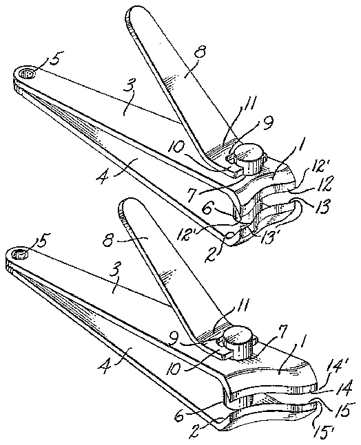
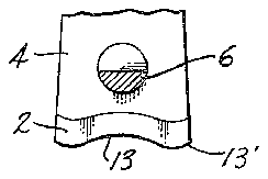
Figure 1 is a top perspective view of a nail nipper having jaws with a continuously curved concavo-biconvex profile, and Figure 2 is a central longitudinal section through the nipper, portions being broken away and the stationary jaw being shown in profile.
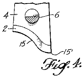
Figure 3 is a top perspective view of a nail nipper hav ing jaws with an ogee curved profile, and Figure 4 is a central longitudinal section through the nipper, portions being broken away and the stationary jaw being shown in profile.
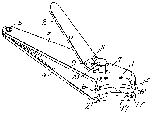
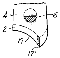
Figure 5 is a top perspective view of a nail nipper having jaws with a peaked ogee curved profile, and Figure 6 is a central longitudinal section through the nipper, portions being broken away and the stationary jaw being shown in profile.
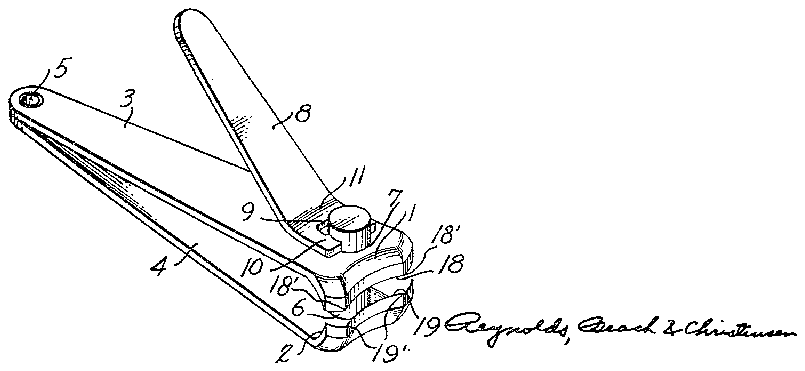
Figure 7 is a top perspective view of a nail nipper having jaws with a double-peaked concavo-biconvex curved profile, and Figure 8 is a central longitudinal section through the nipper, portions being broken away and the stationary jaw being shown in profile.
The various types of nipper shown in the drawings all 2,774,138 Patented Dec. 18, 1956 ice incorporate jaws 1 and 2 formed on the ends of arms 3 and 4, respectively, which are interconnected, such as by a hollow rivet 5 at the end remote from such jaws. On one of the jaws 2 is mounted a guide pin 6 over which fits snugly an aperture 7 in the other jaw 1. Such pin and aperture guides this jaw for accurate movement toward and away from the jaw 2. A lever 8 has a notch 9 in one end forming bifurcations 19 carrying lugs which are pivotally engaged with the end of pin 6 remote from jaw 2.
The arms 3 and 4 are of spring material and, because of their interconnection by the rivet 5, urge their jaws 1 and 2 apart. Separating movement of the jaws is limited by engagement of jaw 1 with the bifurcations of the lever 8. A bent portion 11 of this lever may function as a fulcrum bearing on arm 3 when pressure is exerted on the swinging end of the lever. Force thus exerted by the lever on arm 3 will move the swinging end of such arm and jaw 1 toward the adjacent end of arm 4 and jaw 2 respectively. Such supporting and jaw operating mechanism is conventional and is illustrated merely to show suitable structure for supporting and mechanism for operating jaws having profiles embodying the principles of the present invention.
In the nipper shown in Figures 1 and 2 the cutting edges 12 and 13 are shown as being of continuous concavo-biconvex curvature. The central concave portion of the cutting edges merges with convex portions at opposite ends of such cutting edges. The concavely reentrant curved central portion of these cutting edges extends over a major portion of their length as is evident from Figure 2, and the concavely curved portion merges smoothly and continuously with each of the convex portions. Preferably, as shown, the convex portions are more sharply curved than the concave portion, and as shown, the profile of each cutting edge may be symmetrical about its center. As shown, the outerends of the convex portions of the cutting edges terminate abruptly in sharp corners 12' and 13' so that the convex portions, which are sharpened to such sharp corners, are useful as nippers despite the concave shape extending over the major portions of such cutting edges. Such sharp corners enable the convex cutting edge portions to be used like the portions of manicure scissor blades adjacent to their points.
In Figures 3 and 4 the cutting edges 14 and 15 are of ogee profile, in which the portion of concave curvature again constitutes a major portion of the length of the cutting edges and merges smoothly into the curvature of the convex portion of the cutting edges. In this instance again it is preferred that the convex curvature be somewhat sharper than the concave curvature. By providing only a single portion of convex curvature on the cutting edge, the concave portion of the cutting edge can be made substantially longer than the concave portion of the cutting edge in the type of nipper shown in Figures 1 and 2, the curvatures of the concave cutting edge portion and of the convex cutting edge portion of the nipper shown in Figures 3 and 4 can be made less sharp, respectively,
than the curvatures of the concave cutting edge portionand of the convex cutting edge portions of the nipper shown in Figures 1 and 2. In this construction also, however, the convex portions of the cutting edges terminate abruptly in sharp corners l4 and 15' so that the convex portions, sharpened to such sharp corners, are useful as a nipper.
The profile of the cutting edges on the nipper shown in Figures 5 and 6 is somewhat similar to that of the cutting edges of the nipper shown in Figures 3 and 4. Thus each of the cutting edges 16 and 17, like the cutting edges 14 and 15, includes a concave portion and a single convex portion. In this instance, however, the curvature of the concave and convex portions is discontinuous, such portions meeting at peaks 16' and 17' forming sharp edges are sharpened to 'such'peaks 16' and 17' at which they'terminate abruptly at their junction with the concave portions, so as to formefiective nipper portions.
It is still preferred in the form of; Figures and 6 that the length of the'c'onca've portion of the cutting edges be a major portion of the total length of the cutting edges and the length or the convex portion a minor portion of the total length. Also, as mentioned in connection with the previous types of cut-ting edge pro-file, it is preferred that ends of fingernails or toenails to a pleasing curvature. Provision of the convex portions at opposite ends of the concave portion in the form of Figure 2 eliminates the usual sharp points which can inadvertently be dug into the tissue beneath a nail to cause pain. More important,
however, either-of the'convex portions can be used cona veniently to trim the sides of a nail easily to the desired shape, even-though the nail may be ingrown, and to nip hangnails, comparable to the use of the pointed ends of manicure scissors blades.- 7
The shape of cutting edge shownpon the'clipper of 7 Figures 3 and 4 provides a rounded convex portion havthe curvature of the'convex cutting edge portion'be sharp-.
' er than the curvature of the concave cutting edge portion.
Because 'thecurvatures of the 'convexand concave cutting edge portions are discontinuous, the sharpness of the curvature of either portion can be selected entirely without reference to the curvature of the other portion, the
, only effect being to alter somewhat the angle of the peak formed by the junction of the two curves of each cutting edge. V
1 In the modification shown in Figures 7 and 8 the cutting ,edges 18 and 19 of the jaws have two convex portions,
one ateach end, with a central reentr-ant concave portion generally similar to the arrangement of the two convex portions at opposite sides of the concave portion in the cutting edges 13 and 12 of the clipper shownin'F-igures 1 and 2. In the cutting edgesof Figures 7 and 8,"however, the curvature of the'two convex portions .and' the concave portionbetween them is discontinuous. Thus the concave portions meet the convex portions in peaks 18 and 19 which are sharp corners, forming a double-peaked coning a substantial projection terminating abruptly in sharp corners which is even more easily inserted into portions of the nail side to which access is difficult. The peak and side convex portion shown on the clipper of Figures 5 and 6 may be preferred by some users for a similar manipulation. V 7
7 The convex portions at opposite sides of the concave portion of the cutting edges on the nipper shown in Fig I ures 7 and 8 will be used in a manner similar to the convex portions of the cutting edge shown in Figures 1 and 2.
: ating cut-ting edges of reverse-curve profile, each cutting edge including a concave portion and a convex portion 'rnerging at a point, said concave. and convex portions having their outer ends terminating abruptly in sharp. corners, and such cooperating cutting'ed-ges of said nipper extending to such corners and adapted for engagement cavo-biconvex profile. The concave portion of the cutting edges, however, in this instance also constitutes a major.
portion'of the length of the cutting edges.
Because of the discontinuity between the concave and the convex portions of the cutting edges, the curvature of the concave cutting edge'portion can be altered Without reference to'the curvature of the convex portions, and-the curvatures of the convex portions can :be changed without interference with the curvature of the concave portion. In
this instance likewise, however, it is preferred that the curvature ofthe concave portion be less sharp than the curvatures of the convex portions; and that the convex portions be sharpened to the peaks 1S and 19 at which they terminate abruptly at their junctions with the concave portion-to form nipper portions. Also, as shown,
the cutting edges may be symmetrical about their centers.
In all of the cutting edges illustrated and described a.
major portion of theleng th of the cutting edges preferably is of concave shape to be used for trimming the The peaks between the convex portions and the reentrant concave portion, while adequately abrupt to constitute nipper points are not sufiiciently sharp to be likely to cause injury even when not used with appreciable caution.
I claim as my invention: a i 1. A digit nail nippercornprisin'g jaws having cooper when said jaws are closed. a V
' 2. The digit nail nipper defined in claim 1, in which the concave and convex portions of each cutting edge form a smooth curve through the point of merger.
3. Thejdigit nail nipper defined in claim 1, in which the concave and convex portions of each cutting edge meet at an angle at the point of merger.
4. A digit nail nipper comprising jaws having cooperating cutting edges of reverse-curve profile, each cutting edge including a concave port-ion and a convex portion merging at a point, and each cutting edge having its outer ends terminating abruptly in sharp corners, such cooperating cutting edges or said nipper being adapted for'engagement when said jaws are closed."
. s. The digit nail .nipper defined in claim 4, in which 7 each cutting edge has a convex portion at each end.
References Cited in the file of this patent UNITED STATES PATENTS Schnefel :Feb. 12, 1929 Peters Jan. 19, 1932


