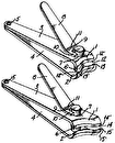

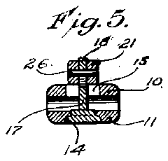
- 1whichigure
- 11members
- 14aperture
- 15aperture
- 17stud
- 18hook
- 19one end
- 20other end
- 21lever
- 22limbs
- 23limbs
- 24shoulders
- 25shoulders
- 26pin
Description
Feb. 12, 1929. 1,702,137
M. SCHNEFEL NAIL CLIPPER Filed lay 16, 1925 WITNFSSES INVENTOR {64x SCHNEFEL Patented Feb. 12, 1929.
PATENT OFFICE.
I m scmwmn, O1 NEWARK, NEW JERSEY.
NAIL CLIPPER.
'Application filled Iay 16, 1925. Serial v17o. 30,199.
This invention relates to a nail clipper. One of the-main objects of the invention is to rovide a nail dlipper which, by reason of 1ts ,coristruction is simple, compact, durable and formed of a minimum number of parts which can be readily assembled and disassem bled, and when the parts are in closed position there are no protruding corners or sharp edges.
A further object concerns the provision of a simple and efficient clipper in which the operating lever is also adapted to act as a locking member when the parts are in their closed position.
A still further object concerns the prov1- sion of a simple and efiicient construction wherein the various parts can be finished individual ly and then hooked together ready for use.
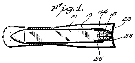
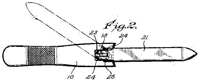
The invention is illustrated in the drawin s, of whichigure 1 is a plan view of the parts closed; Fig. 2 is a similar view of the parts in open position showing in dotted lines the operating lever moving to the position shown in full lines therein;
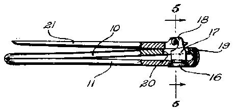
Fig. 3 is a side elevation of the clipper with.
the parts in the position shown in Figure 2; F 1g. 4 is a side elevation, partly in section, showing the parts in the position with the operating lever fully depressed and the members together to produce a cutting action; and
Fig. 5 is a section on the line 5-5 of Fig. 4.
The form of the invention shown in the' drawings is a preferred form, although it is understood that modifications in the construction and arrangement of the parts and in the character of the materials used may be adopted without departing from the spirit of the invention as set forth in the appended claims.
In its general aspect, the invention comprises a plair of springlike flat strips connected togetedges on the opposite ends. These cutting edges are adapted to be forced together to er at one end and having cutting end having a pin mounted therein is adapted to extend partly through the aperture in one of said members to engage the hook portion of the stud. This operating lever is provided with a cam surface so that when moved to a certaln position anddepressed'it will force the two members together to produce a cutting action. When the operating lever is released it wil immediately spring to an open position, due to the resiliency of the members. When turned to a predetermined position and then moved in a plane parallel to one of said members, either to the right or to the left, this operating lever will act to lock the strips or members together and to present an outer configuration substantially flat and entirely smooth so that there are no projectingparts to catch in the clothes or tear the garments. K V
The preferred form of the invention is shown in the drawing and comprises a clipper formed of a pair of spring plates or members 10 and 11 connected together at adjacent ends and normally spaced apart at the other end. These free ends are rovided with cutting edges 12 and 13. T ese free ends are also provided withapertures 14and 15. The aperture 14 is preferabl round and adapted to receive the head 16 of a stud 17. The upper end of this stud is provided with a hook, 18. The stud itself is flat and is adapted to project upthrough the aperture 15. The
aperture 15 is preferably "elongated, one end 19 being curved and the other end 20 being straight edged. 'Preferably the stud 17 extends up through the aperture 15 near the curved end thereof which is located near the free end of the plate or strip 10.
An 0 erating lever 21 is provided with one end split in the form of a fork having limbs 22 and 23 projecting from the end. This lever is also provided with curved-cam shouldcrs 2-1 and 25 near the end of the main body portion of the lever 21. forked end of the operating lever are ada ted to extend on opposite sides of the stu 17, and a pin 26 projects across between the limbs of the forked end'to be engaged beneath the hook 18 on the upper end of the stud.
The stud 17 is rotatably mounted in the hole 14 in the bottom plate or member 11 so that the operating lever can be rotated. In the position shown in Fig. 1, the operating lever lies flat on top of the member 10 with the limbs of the forked and projecting beyond The limbs of the the curved edge of the aperture 15 by reason of lying beyond the edge of the curved aper tion in Figures 2 and 3, the limbs of the forked end will pass down through the aperture on either side of the stud 17. When the operating lever is moved toward the position shown in Fig. 4, which is its full opera ing position, the shoulders 24 and 25, being curved and acting somewhat as ders, will engage the upper surface of the of member 10 to cam shoulmember-lO, and that the pin 26 as a fulcrum under the hook 18, will cause the depression bring the cutting edge 12 against the cutting edge 13. y Y
It will also be observed from the construction of Fig. 4 that if the members 10 and 11 are held together while the operating lever 21 is moved to a vertical position, the pin 26 can be withdrawn from beneath the hook '18 and separated therefrom. The stud'17 will then drop out of the aperture 14 and this will permit the parts to be separately cleaned or repaired or otherwise attended to. By reason of this ready capacity to disassemble the parts, they may be finished or manufactured separately. and then readily hooked together. As previously mentioned, the relation of the stud 17 to the aperture 15 is such that it is not exactl in the center of the aperture, so that the fbrked ends of the lever will in one position project beyond the end of the aperture as shown in Fig. 1, whereas in the other position the forked ends will lie within the aperture so as to be able to be all lines in Fig. 2,
- lever into locking moved thereinto through the movement of the operating lever. These forked ends moving and lying on opposite sides of the stud W1 1 i also act as. means for giving a certain rigidity to the movement of the operating lever, rendering the parts more rigid and certain in their action.
What I claim is 1. A nail clipper comprising a pair of resihent blades directly connected together at one end and resiliently spaced apart at the other end, said blades having'aligned apertures ad acQnt the cutting edges thereof, a stud rotatably mounted in one of said a ertures and having a hooked end exten ing through the other of said apertures, said last mentioned aperture being of elongated formation with a curved end and a straight edged end, a forked operating lever straddling the stud and having cam shoulders near itsforked end, and a pin in the forked end "adapted to engage beneath the hook, whereby said operating lever'is pivotally movable in vertical and horizontal planes, to bring the position or into position for moving the blades into cutting engagement.
2. A nail clipper comprising two connected resilient members one above the other, the lower member being provided with a round opening and the upper one with a slot, a flat stud having a head at one end and ahobk at the other end, the stud being mounted to turn in the opening and projecting through the .slot, and an operating lever having a forlted hooked end of the stud projects, said lever being provided between its limbs with a pin engaging the hook of the stud and adjacent said forked end with cam normally outer face.
MAX SCHNEFEL.
end between the limbs of which the surfaces on its

