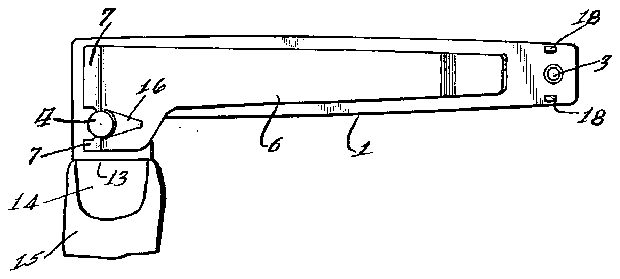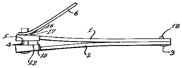


- 2leaves
- 4stud
- 5notch
- 6lever
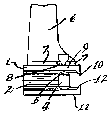
- 8cross-piece
- 9projection
- 10cutting edges
- 11similar lateral projection
- 12cutting edges
- 14nail
- 15toe
- 16cam
- 17cam formation
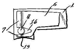
- 19y
Description
y 7, 19 3 M. R. LEVlTT 3,088,204
NAIL CLIPPER Filed Sept. 14, 1961 INVENTOR. lfi/fazz R. lei ff 3,088,204 NAIL CLEPER Milton R. Levitt, New Brunswick, NJ., assignor to The Scholl Mf Co., Inc., Chicago, 111., a corporation of New York Filed Sept. 14, 1961, Ser. No. 138,079 7 Claims. (Cl. 30-28) This invention relates to improvements in a nail clipper, and more particularly to a nail clipper especially designed for toenails, although it may be used for fingernails as well, as will be apparent to one skilled in the art.
In the past, both nail nippers and nail clippers have been developed. Nail nippers of the overall or general purpose type, that is for both finger and toenails, and which resemble the commonly known wire nippers, must of necessity sell at an objectionably high price. On the other hand, fingernail clippers, comprising a pair of superposed elongated leaves secured together at one end and resiliently urged apart at the other end, which other ends have confronting knife edges, the leaves being urged together to close the knife edges by a pivotal lever disposed above one of the leaves, could and have been sold at a reasonable or nominal price, but have proved inefiectual and impractical for use on toenails owing to the small size and consequent poor leverage as well as the fact that the knife edges were laterally curvate and toenails should be cut straight across. A larger version of the old and well known fingernail clipper has been developed for use with toenails, this version differing from the previously known fingernail clipper mainly in size so as to provide adequate leverage for the cutting of toenails. However, with the knife edges disposed transversely to the longitudinal axes of the leaves bearing those edges, such device was both inetficient and unsafe to use for toenails, and in most cases it was substantially impossible or impractical to properly trim a toenail. That is because the device must be held with the hand in an inverted position and an awkward bend in the wrist so that the device is disposed directly in front of the toe being worked upon. When such clippers were utilized for fi-n- 'gernails that difliculty did not occur because the hand and fingers can readily be turned sidewise to accommodate the device. So, even though heretofore a device has been produced of the clipper style for toenails, it has proven unsatisfactory and unsafe to use for that purpose.
With the foregoing in mind, it is an important object of the instant invention to provide a nail cutter of the clipper type, so constructed that toenails may be easily, safely, and properly trimmed.
Another object of the invention is the provision of a nail clipper, constructed for the trimming of toenails with the hand of the operator disposed in a relaxed and natural positionzand With the actual line of severance of the nail plainly visible to the user at all times.
Also a feature of this invention is the provision of a nail clipper, highly desirable for the trimming of toenails, and embodying a pair of leaf members resiliently held separated at one end, these members being provided with confronting knife edges at that end but with the knife edges substantially paralleling the longitudinal axes of the leaves.
It is also a desideratum of this invention to provide a nail cutter of the clipper type embodying a pair of spring leaves or the like carrying confronting cutting edges, but with the cutting edges disposed at the sides of the leaves adjacent one end of the device, rather than across the forward edges of the leaves as has been done heretofore.
Another object of this invention is the provision of a nail cutter of the clipper type with a cutting member carried on each of a pair of spring leaves at the sides of 3882fi4i Patented May 7, 1963 the leaves, and with the knife edges of the cutting member so arranged to come together intimately throughout their length when the spring leaves are urged toward each other.
Still a further object of this invention resides in the provision of a simple form of nail clipper, highly suitable for the trimming of toenails, with cutting edges disposed at the side of the clipper, rather than at the end thereof, and which cutting edges may be straight or slightly cu-rvate as desired.
While some of the more salient features, characteristics and advantages of the instant invention have been above pointed out, others will become apparent from the following disclosures, taken in conjunction with the accompanying drawings, in which:
FIGURE 1 is a plan view of a nail clipper embodying principles of the instant invention showing the same in operative position for the trimming of a toenail;
FIGURE 2 is a fragmentary side elevational view of the clipper itself;
FIGURE 3 is a fragmentary end View of the clipper taken from the left-hand side of FIGURE 2; and
FIGURE 4 is a fragmentary plan view showing a slightly modified form of construction.
As shown on the drawings:
In the first illustrated embodiment of the instant invention, seen in FIGURES l, 2 and 3, the clipper includes superposed spring leaves 1 and 2 having confronting faces secured together adjacent one end of the device by a rivet 3 or the equivalent. By virtue of their own resiliency, the spring leaves tend to separate from each other at the opposite end of the device as seen best in FIGURE 2. The separation of the leaves 1 and 2 is limited by means of a stud 4 fixed in the lower spring leaf 2 and freely projecting through a suitable aperture in the upper spring leaf. The stud 4 is provided with a notch as indicated at 5, and an actuating lever 6 having a bifurcated forward end portion 7 with the furcations disposed on opposite sides of the stud 4, also has a cross-piece 8 between the fu-rca-tions 7 engaged within the notch 5.
At the spread separated ends thereof the leaves 1 and 2 are provided with laterally disposed knife edges. The leaf 1 has a lateral projection 9 thereon, which may be attached to the leaf or integral therewith as may be preferred, and this projection carries a downwardly turned knife or cutting edge 10 which projects beyond the adjacent confronting face of the leaf. The leaf 2 has a similar lateral projection 11 carrying an upwardly turned and projecting knife or cutting edge 12 confronting the edge 10. The edges are normally spaced apart by the resiliency of the leaves 1 and 2, and are only brought into contact with each other when a cut is being made. It will be noted from the showing in FIGURES 1 and 2 that the cutting edges 10 and 12 are preferably straight and substantially parallel to the longitudinal axes of the leaves 1 and 2.
It will be noted, however, that the cutting edges 10 and 12 are deeper at their outer ends than they are at their inner ends, and gradually decrease in thickness toward the inner ends, whereby when the spring leaves 1 and 2 are moved toward each other the cutting edges will contact evenly and intimately throughout their entire length to insure a proper and clean cut. It should also be noted that the means to close the leaves, comprising the actuating lever 6 are located between the longitudinal axis of the leaf 1 and the adjacent knife edge '10, and, more particularly, extends further laterally toward the cutting edges from the longitudinal axis of the leaf 1 than toward the opposite side of the leaf, so that one of the furcations 7 and the stud 4 are over the projection 9 on the upper spring leaf 1, whereby when the actuating lever is pressed, pressure is applied immediately adjacent the cutting edges.
As is well known to physicians, chiropodists, podiatrists, and the like, in order to avoid ingrown nails, toenails are preferably cut straight across rather than given an arouate configuration as is the case with fingernails. The straight edges and 12 on the instant clipper readily provide the desired straight out as indicated at 13 in FIG- URE 1 where the device is shown as trimming a nail 14 on a toe 15.
In operation, the instant invention is extremely simple to use, safe, and accurate in trimming. It is a simple expedient to place one or more fingertips beneath the leaf 2, and the thumb on the actuating lever 6, or vice versa, and press the lever 6 toward the leaf 1. It will be noted from the showing in FIGURE 2 that the forward end of the lever 6 is bent in the region of the furcations at an angle to the remainder of thelever, and a cam 16 on the underside of the lever operates against a cam formation 17 on the upper leaf 1 to force the leaves 1 and 2 toward each other and bring the cutting edges 10 and 12 together to trim a nail. It will be noted that during this operation the hand is in a normal and easy position substantially at right angles to the nail being worked upon, the line of out is readily visible, the nail is cut accurately and safely, and there is no awkwardness involved in the operation which may be accomplished in connection with toenails in far less time than was possible heretofore with the formerly known clipper. When the device is not in use, it is a simple expedient to pivot the lever 6 forwardly until it is in inverted position, then turn it laterally and drop it upon the upper leaf 1 with the rear end of the lever seated between a pair of upstanding lugs 18-18 on that leaf.
In FIGURE 4 I have illustrated a slightly different form of the invention, wherein the knife edges are given an arcuate shape as indicated at 19. Otherwise the struc ture is. the same as previously described. The arcuate shaped knife edges are still disposed on the side of the device rather than at the end thereof and are possibly of a more desirable shapefor fingernail trimming or for those who also desire [an arcuate cut to a toenail notwithstanding the recommended straight cut. The device is operable in the same manner as the previously described structure and just as easily.
From the foregoing, it is apparent that I have provided a simple form of nail clipper, highly desirable for use in trimming toenails, which is operable in an easy natural and safe manner, which is highly durable, and may be economically manufactured.
It will be understood that modifications and variations may be efifected without depanting from the scope of the novel concepts of the present invention.
I claim as my invention:
1. A nail clipper comprising a pair of superposed leaves secured together at one end of the clipper and resiliently separated at the other end, confronting knife edges one on the side of each leaf in the region of leaf separation, and means to close said leavesto bring the knife edges into cutting relationship, said means extending farther laterally toward the knife edges from the longitudinal axis of the upper leaf than toward the opposite side of the leaf to apply pressure immediately-adjacent the cutting edges.
2. In a nail clipper, a pair of elongated flat leaves in superposed relationship and secured together adjacent one end of the clipper and resiliently separated at the other end, a lateral extension on each said leaf adjacent the unsecured end thereof, and downwardly and upwardly extending confronting knife edges on the upper and lower extensions, respectively. 7
'3. In a nail clipper, a pair of elongated fiat leaves in superposed relationship and secured together adjacent one end of the clipper and resiliently separated at the other end, a lateral extension on each said leaf adjacent the unsecured end thereof, and downwardly and upwardly extending confronting knife edges on the upper and lower extensions, respectively, said knife edges being straight and generally paralleling the longitudinal axes of said leaves.
4. In a nail clipper, a pair of elongated flat leaves in superposed relationship and secured together adjacent one end of the clipper and resiliently separated at the other end, a lateral extension on each said leaf adjacent the unsecured end thereof, and downwardly and upwardly extending confronting knife edges on the upper and lower extensions, respectively, said knife edges being concavely arcuate but generally paralleling .the longitudinal axes of said leaves.
5. In a nail clipper, a pair of spring leaves secured together at one end of the clipper rand inherently separating at the other end, a knife edge on the side of each leaf adjacent the separated end, said knife edges confronting each other, said knife edges being deeper at the outer ends than the inner ends and gradually decreasing in depth toward the inner ends to insure contact throughout the full lengths thereof, and means to close said leaves to bring the knife edges into cutting relationship, said means being located between the longitudinal axis of one of the leaves and the adjacent knife edge so as to apply pressure immediately adjacent the cutting edges.
6. In a nail clipper, a pair of elongated flat leaves in superposed relationship and secured together adjacent one end of the clipper and resiliently separated at the other end, a lateral extension on each said leaf adjacent the unsecured end thereof, and downwardly and upwardly extending con-fronting knife edges onthe upper and lower extensions, respectively, means to close said leaves to bring said edges into cuttingrelationship, said means projecting laterally over said extensions to apply pressure immediately adjacent the cutting edges.
7. In a nail clipper,
a pair'of'spring' leaves having confronting faces secured together in face-to-face relation at one end of the clipper and inherently separating at the other end,
a knife edge on the side of each leaf adjacent the separated end and projecting beyond the con-fronting face of the respective leaf,
said knife edges confronting each other and gradually decreasing in depth toward their inner ends to insure even contact when brought together,
and means to close said leaves to bring the knife edges into cutting relationship,-
said means being located between the longitudinal axis of one of the leaves and the adjacent knife edge so as to apply pressure immediately adjacent the cutting edges.
References Cited in the file of this patent UNITED STATES PATENTS


