- 2bowers
- 5t
- 20my nail clipper
- 21shell members
- 22shell members
- 23chamber
- 25spring
- 26vat
- 27weld
- 28clevis
- 30tongue extension
- 31recess
- 32surfaces
- 35spur
- 40nail cutting edges
- 41nail cutting edges
- 45lever
- 46lever working arm
- 47fulcrum
- 48power arm
- 50channel
- 51edges
- 52floor
- 55spring
- 57la slot
- 58pins
- 59end
- 60bearing
- 62bearing
- 63point
- 64horn
- 66bay
- 67edge flanges
- 68surfaces
- 70cutting edges
- 71cutting edges
- 146working arm
- 322shell `members
- 626bowers
- 753bowers
Description
July l0, 1956 T. s. BOWERS 2,753,626
NAIL CLIPPER Filed April 29, 1955 Y Q INVENTOR.
./fzomad. oww/J.
United States 'Patent O NAIL CLIPPER Thomas S. Bowers, Meriden, Conn., assigner of one-halt to Herbert N. Archambault, Toledo, Ohio Application April 29, 1955, Serial No. 504,946
9 Claims. (Cl. Sil- 28) My invention relates to the cutting arts and particu larly to manicuring devices known generally as nail clippers. More specifically, my invention deals with the pocket variety of nail clippers, such as those adapted to be conveniently carried either in a ladies purse or a mans pocket as a fob for a key or watch chain and the like.
Examples of the pocket variety of nail clippers familiar to the art are those shown and described in United States Patents Nos. 504,601; 775,568; 846,565 and 846,- 924 issued September 5, 1893; November 22, 1904; March 12, 1907 (two patents) respectively to E. T. Mason; F. B. La May; G. Havell and O. Kampfe respectively. One of the major objects of my invention is to improve greatly upon the adaptability, compactness, appearance and utility of the pocket type nail clipper known to the art.
One fault of many of the structures of the prior art, exemplified by the La May patent structure, which I propose by my invention to remedy, is the need to swivel the clipped operating lever through 180 in order to put the lever, when in non-operating position, into an operating position or vice versa. This makes operation of such device gawky and clumsy and, for some, of such diflculty as to neighbor impossibility.
Another fault of the prior art which I propose to correct is the generally exposed nature of the operating parts of these earlier devices which, in being carried in the pocket of the user, causes frictional abrasion and undue Wear of the pocket.
A still further fault of the prior art which I expect my invention to cure is that entirely functional and unaesthetic appearance such devices make in relation to such commonly carried pocket pieces as the conventional ladies compact, cigarette lighter, key case and the like. By my invention, I propose to provide a nail clipper having a compatible appearance to these companion pocket pieces, thus making the carrying and use of the nail clipper more readily acceptable and tasteful among people generally.
In addition to correcting the faults of the prior art,
my invention proposes to advance the art in several re` spects. To this end, my invention has for an object to provide a nail clipped in which at least one of the nail cutting members comprises a dished shell into which the portion of the nail to be cut away is inserted, preparatory to cutting, and which, as a consequence of severing and after such cutting, will be entrapped within the shell, instead of being permitted, as in the use of prior art devices, to fall helter-skelter to one side, requiring later retrieval for disposal.
Another object of my invention is to provide housing within the contour of one of the nail cutting members body for enclosing the clipper actuating lever, when said lever is in its non-operating relation. Thus, I materially improve the clipper by reducing its overall size in proportion to the nail cutting edges it possesses and I also eliminate otherwise exposed pocket material abrading edges and parts.
2,753,626 Patented July 10, 1956 ICC A still further object of my invention is: to provide a clipper actuating lever characterized by the fact that in clipper non-operating relation the lever is unclutched from the nail cutting members wherefore accidental movement of the lever, as would in the prior art cause clipper actuation, cannot, in clippers embodying my invention, cause such unintended and often damaging clipper actuation.
Related to the foregoing object is this other object of my invention to provide, by an arrangement of parts, a means whereby the clipper actuating lever may move automatically from a non-operating unclutched relation to an operative clutched relation, upon a user directed pressure to a point on the lever within the contour of one of the nail cutting members. Thus, the happenstance cocking or enclutchment of the clipper actuating lever in a clipper embodying my invention is negligible, without sacrifice of that desired degree of an automatic readiness tov operate to which some of the prior art devices aspire.
Supplementary to the foregoing objects, my invention also seeks to provide an ambidexterous nail clipper having dual nail cutting sets on either side of the clipper actuating lever. This provision enables the user to clip both right and left hand with equal facility. In a sense, the fulfillment of this object my invention advances the art over the attempt to solve this same problem exhibited by H. Wilcox in his United States Patent No. 702,516 issued June 17, 1902.
My invention has for further objects to provide other advantageous structures and arrangements which will appear from the following description and an examination of the accompanying drawings. Structures containing my invention may take various forms. I have selected a nail clipper which constitutes a specific embodiment of my invention and shall describe the same hereinafter since it now appears to me as the best mode of carrying out my invention. Reference to the accompanying drawing has been had to facilitate such description. In making such description or using the accompanying drawing for reference, I do not imply, however, that variation from the chosen structure, which do in fact embody my invention manifest herein, are beyond the contemplation of my invention.
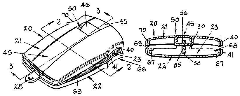
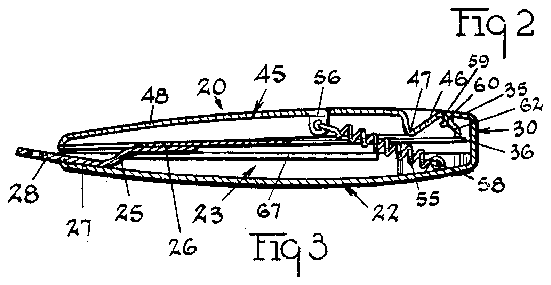
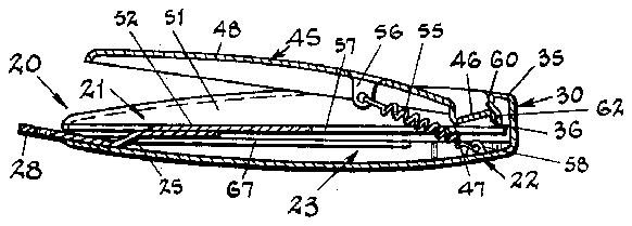
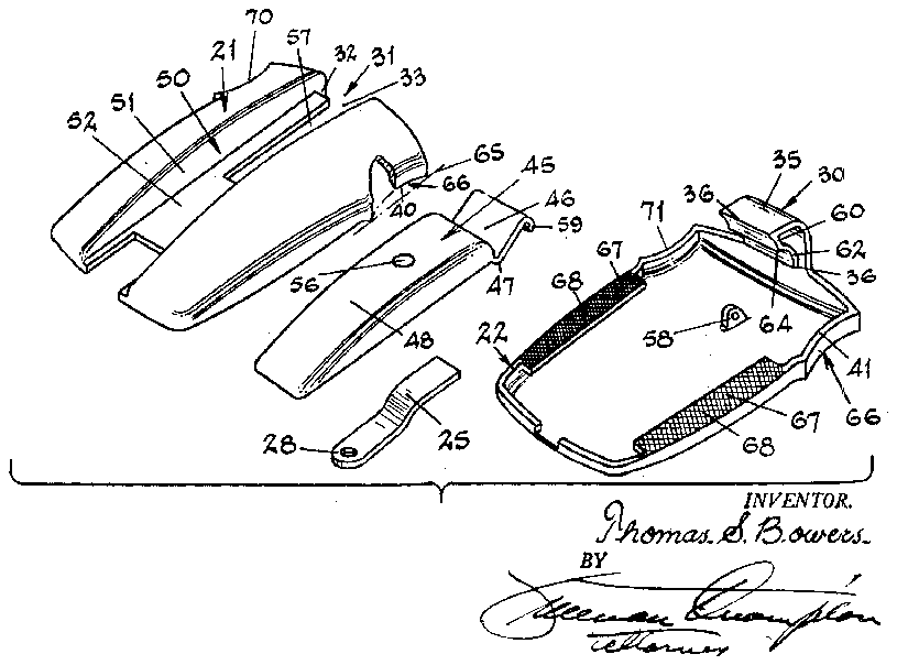
Figure 1 illustrates a perspective view of a nail clipper embodying the features of my invention and. which I have selected to describe herein for illustrative and statutory purposes. The nail clipper shown in Figure 1 has its parts in their pocketing non-operating positions. Figure 2 illustrates an enlarged view of a section taken along the plane of the line 2-2 indicated in Figure 1. Figure 3 illustrates an enlarged view of a section taken along the plane of the line 3 3 indicated in Figure 1. Figure 4 illustrates, from the same plane as that of Figure 3, the appearance in section when the clipper parts have moved to their operative relations for nail clipping. Figure 5 illustrates an exploded assembly view of the parts which comprise, when assembled as will be described, the nail clipper shown in Figure 1.
In the accompanying drawings the nail clipper I have` selected to illustrate embodiments of my invention is generally indicated at 20. As will be seen, such nail clipper has two cooperating nail cutting members 21 and 22. The nail cutting members may be formed from metal or, with suitable reinforcements to provided fracture resistance and anvil hardness where needed, plastics may be used to good advantage. Preferably, the members 21 and 22 are dished shells of similar outline as I have .shown in the accompanying drawing. By such provision, the shell members 21 and 22, when associated together in facing registering relation, form a hollow chamber 23.
In order to hold the members 21 and 22 inthe associated relation I provide means connected to each member which connects the members together but permits angular movement only by each member relative to 'the other. This hinge like acting means may have yieldably flexible characteristics tending to bias the members to angular movement away from each other. Such structure is incorporated 'in the spring 25 which may be spot welded `or otherwise aixed, as vat 26, to member 21 and, as at 27, t0 the 'member 22. y
If desired, the spring may have a clevis 28 projecting outwardly from between the shells 21 and 22 -to which a key chain snap or the like may be attached by the user.
In order to limit the biasing effect of the spring 25 on the shell member parts 21 and 22 and to .guide the relative movement thereof, I provide one of the shell member parts with a tongue extention. For example, in the construction shown in the accompanying drawings, the shell 22 has an integral tongue extension '30. The extension 3@ extends from points on the shell 22 in spaced relation to the weld 27 connecting the spring 25 to said shell 22. In the sense that the shell end to which the spring 25 is connected by the weld 27 is the tail end of the shell 22, the tongue extension 30 projects from the head end of the shell 22 and is medial to the width of the shell. The tongue extension -30 projects at nearly right angles to the major plane of the shell 22 and in a direction toward the shell 21 and to points on the side of said shell 21 which face away from the shell 22.
To provide the cooperating bearing for said tongue extension and at the same time add to the attractive design of the nail clipper, the head end of the shell 21 has a recess 31 through which the tongue extension projects. The recess has side surfaces 32 sufficiently spaced from each other to permit the extension 30 to pass therebetween and a bottom surface 33 suiiciently deep to permit the tongue extension to lay Within the contour lline of the head end of the shell 21. The surfaces 32 and 33 slidingly engage with surfaces on the tongue extension 30, acting as bearing guides tending to prevent the shell member parts 21 and 22 from tilting or cooking relative to yeach other as they move about the hinge axis provided by the spring 25.
The tongue extension 30 has a tip end extending substantially parallel to the shell 22 provided with what I have chosen to call a spur 35. The spur 35 includes a stop part 36 positioned in the path through which the shell member 21 would move in response to the bias of the spring 25 were it not for the stop part 36. Thus, when the shell member 21 engages the stop part 36 of the spur 35, Athe further movement of the shell member l21 away from the shell member 22 terminates and the relative movement of both shell members 21 and 22 toward and away from each other is restricted to a relatively short stroke, even as little as an eighth inch or so.
Any much greater stroke than the mentioned one` would be unnecessary since all that is needed is one suicient to eifect separation of the shell member parts as will allow the insertion of the users linger nail edge to be clipped between nail cutting edges carried on the shell member parts.
Such nail cutting edges may be in pairs like the pair of nail cutting edges 40 and 41 shown in the drawings. As is conventional at least one edge, say the edge 40, is ksharp and the other, like the edge 41 may be either sharp 0r blunt. If the edge 41 is blunt, as shown, it forms the anvil or cutting platen against which the sharp edge '40 acts to clip a nail placed therebetween. Whether the edge 41 is sharp or blunt is not, however, critical to my .invention. I do, on the other hand, regard the disposition of the pair of nail cutting edges 40 and 41 in reference to the clipper operating lever, soon to be described, and the provision and disposition of an additional pairof nail ycutting edges, like the ones marked 40 and 41, as important features of my invention. Suice itfor now `to observe that movement of the shell member parts 21 `and .22 towards each other about `the axis provided by the spring 25 causes the shell member edges 40 and 41 to engageand, between them, to sever or clip a nail.
To facilitate moving the shell member parts 21 and 22 towards each other, I provide, as previously mentioned, an operating lever 45. The lever 45 may be, as shown, a bent or dog-leg lever of the first class having a working arm 46, a fulcrum 47 and a power arm 48. The lever 45 is supported on one of the shell members 21 and 22. As shown in the accompanying drawings, the lever 45 is supported on the shell member 21. To house the lever 45 and thereby to support it, the shell member 21 has centrally disposed, longitudinally extending open channel 5t).
The channel 50 has side edges 51 spaced sufficiently to enable the lever 45 to nest between said edges 51. The channel 50 also has a oor 52 on which the lever fulcrum 47 may rest and press in the operation of the lever. The floor 52 and edges 51 of the channel also provide a slide bearing for supporting the lever 45 for movement from a non-actuating disenclutchment with the shell `members 21 and 322 to an lactuating enclutchment therewith.
In order to retain the lever 45 on the shell member 21 and in the channel -50 thereof and at the same time allow the lever a degree of free movement, relative to said shell member, necessary to move to and from disenclutching to enclutching relation and to subsequently actuate the shell members, I connect the lever 45 to the assembled shell members by means of a flexible connection, such as the wire coil spring 55. One end of the spring 55 is connected to the lever 45, preferably at a point between the `fulcrum 47 and the free end of the power arm 48 thereof. A swivel stud, dowel or pin 56 in `the lever arm 48 provides such connection with the spring end. Preferably, as shown in the accompanying drawings, the spring 55 extends through la slot 57 provided in the channel floor '32 to a point on the shell member 22 near the base of .the tongue extension 30, at which point -the other end of the spring 55 may be connected. As shown, t-he connection heremay be-also made to a swivel stud, dowel or pin A58 like that shown at 56.
.By virtue kof the cant of spring 55 between the pins 56 and 58 and its distortion when stretched between such pins, the llever 45 is bodily biased to move in a-n endwise direction `through the channel 50 with the free end 59 of the V.lever working arm 46 leading. In yielding to this bias, the -lever 45 moves to its disenclutched and enclutched positions, respectively. These positions, are determined principally by the engagement of the end 59 of the lever working ar-m 46 with bearings on the spur 35.
The first bearing 60 on -thespur 35 is adapted to receive and engage the end v59 of the lever working varm 46. The bearing f60 preferably vis of -a shape that mates with that of the end 59. The bearing 60 is spaced as shown Vin the accompanying drawings, Ifrom lthe stop part 36 ofthe spur 351a distance not less `than the height of the fulcrum 47 and, preferably, fa distance slightly in excess thereof. By virtue of this provision, the lever, when responding to the urge of the spring 55 and having its end 59 of its working arm 146 in engagement with ythe bearing 60, will lay at rest inthe channel 50. The-power arm 48 of the lever will then lay close to and in engagement with the channel floor 52. In such position, pressure against the power arm -48 will :notproduce -leverage about the lever fulcrum 47. Movement vof the power arm will be resisted bythe member :21. In this fposition, the lever 45 may be said to be in non-operating disenclutched Vrelation to the shell members -21 and 22.
The operating enclutched relation of the lever45 occurs when the 'end 59 of the lever working arm 46 engages a bearing-62. The second bearing 62 is on the spur 35 adjoining the first bearing 60 and, in lthe line of biased movement of the lever 4S produced by 'the spring 55 vis successive -to .and behind .the ,position occupied by vthe bearing :60. .'.lhe bearing 62, like the bearing 60, has a mating of tting .shape with the -end 59 of the lever working arm 46. Space-wise on the spur 35, the bearing 62 is between the bearing 60 and the stop part 36 and is thus much closer to the shell members 21 and 22. Particularly, the bearing 62 is in a position such that when the end 59 of the lever working arm engages said bearing, the longer power arm 48 0f the lever extends from its fulcrum 47 in inclined relation to the shell member 21 and outside the channel 50. Now, if the free end of the lever power arm should be pressed toward the shell member 21, the lever through its fulcrum 47 would press against the floor 52 of the channel and, through the lever end 59 pressing against the bearing 62, would draw the shell member 22 toward the shell member 21, until the respective cutting edges 40 and 41 of the members engage. I call the position in which the lever end 59 engages the bearing 62 the` lever enclutched position because the lever, as described, is then in a power transmitting relation with the shell members.
Movement of the lever to effect disengagement of the end 59 from the bearing 60 and engagement with the bearing 62 is produced by the user exerting a slight inward pressure on the lever arm 46. Such pressure causes tilting of the lever 45 about its fulcrum 47 enabling the lever end 59 to move over the bearing 60 and a horn 64 on the spur 35 separating and formed by the juxtaposition of the bearings 60 and 62. When the lever end 59 passes by the horn 64, the spring 55 biased the lever endwise to eifect seating of the lever end 59 against the bearing 62, with a snap automatic action. Thus, the movement of the lever 45 from non-operating to operating position occurs with push-button alacrity. The disposition, however, of the lever arm 46 within the channel 50 and below the edges 51 thereof, when the end 59 is not engaging bearing 62, guards against accidental pressure on the point 63, as would effect unintended engagement of said lever end with the bearing 62.
Thus, I provide a lever means for easily pressing the members 21 and 22 towards each other and, by cooperation of the cutting edges 40 and 41 of said members, a nail clipping means of attractive compactness and utility. In addition to the features mentioned, however, I contemplate the advantages in disposing the nail cutting edges 40 and 41 in a relation to the line of action of the lever 45. Such relation is illustrated in the accompanying drawings.
It will be noted that the edges 40 and 41 are of arcuate continuity and in concave relation to the shell members on which they are formed. The arcuate edges extend between the ends of line (indicated at 65) which extends substantially parallel to the lever 4S. Thus, the edges 40 and 41 form a bay 66 facing and opening away from and to one side of the lever 45, said bay 66 providing space into which the user may insert the end of a finger nail to be clipped.
In addition to the cutting edges 40 and 41 whose shape and position I have described, I also provide a second pair of cutting edges 70 and 71 on the members 21 and 22. The cutting edges 70 and 71 are counterparts of the edges 40 and 41. Edges 70 and 71, however, occur on the opposite side of the lever 45 and face in an opposite direction to that faced by edges 40 and 41. By this provision, the edges 40 and 41 may be used to cut the nails on one hand of the user and the cutting edges 70 and 71 used to cut the nails on the other hand. Hence, the clipper may be used ambidextrously and with facility in either hand.
Still another feature of my invention remains to be mentioned. This feature comes as a consequence of the use of the dished shell members 21 and 22 as the cutting edge bearing and main operating parts of my clipper. These shell members, besides housing such parts as the described springs and 55 and other related operating parts, provide, by the chamber 23 within the members 21 and 22, a trap for the selvedge debris of nail clipping. Thus, instead of the severed nail clipping falling, as it is severed, haphazardly about, each clipping will fall into thechamber 23 and be retained there for later and desired disposal. i
If desired, one of the shell members 21 and 22 may have edge flanges 67 having knurled or file-like surfaces 68. The user may draw his nail over the surfaces 68 to remove burrs and to generally smooth the nail edge completing the manicure.
Thus, it Will be seen that my nail clipper 20 described herein has many features and advantages and, in appearance, form and function, is fully compatible with modern pocket pieces carried by men and women alike.
I claim: f
l. A nail clipper comprising a pair of members; means in engagement with said members for hingedly connecting them together; each member having an edge in spaced relation to the point of engagement thereon of said hingedly connecting means and adapted toengage each other on movement of said members towards each other about said hingedly connecting means and means including a manually operable lever for moving the members towards each other about the axis of the means hingedly connecting said member; means in engagement with said lever and one of said members for connecting the lever to one of said parts; one of said members having a channel dimensionally adapted to receive said lever within the channel and to slidably engage said lever to thereby provide a housing and bearing for said lever.
2. A nail clipper as described in claim l in which each of the members has a second edge; said second edges being in spaced relation to the point of engagement of the means hingedly connecting said members; and in which the rst named and second edges are on opposite sides of said channel; one of said second edges being sharp and adapted to engage the other of said second edges when said members move towards each other whereby one of said edges provide a right-hand nail clipper means and the other of said edges provide a left-hand nail clipping means.
3. A nail clipper as described in claim 2 in which the iirst named and second edges are each of arcuate continuity in concave relation to the members and extend between the ends of a line spaced from and substantially parallel to the line of extension of said channel to thereby provide arcuate headed bays in said members on opposite sides of said lever and facing in opposite directions therefrom; said bays providing areas into which a nail to be clipped may be projected to be engaged by said edges.
4. In a nail clipper including the combination of a pair members, means in engagement with each member for hingedly connecting the members together; each member having an edge to engage a like edge of the other member on relative movement of the members towards each other, one of said edges being sharp and adapted upon engagement of the said other edge to clip portions of a nail disposed between said edges; a means for moving the members towards each other comprising a lever on one of the members and on that side of said member facing away from the other of said members and free to move with respect thereto, an extension on said other member in spaced relation to the point of engagement thereof by the member hingedly connecting means, said extension extending toward the named one member to a point beyond that side thereof on which said lever is, said extension having a bearing near its end on said lever side of the named one member, said bearing adapted to bearingly engage with the work arm of said lever, means in engagement with said lever and one of said members biasing said lever to move in a direction toward said bearing and toward locating the lever work arm in engagement with said bearing, said bearing having a spaced relation to said members and the lever fulcrum that when engaging said lever work arm the movement of the lever power arm in one direction about the lever fulcrum causes the members to move towards each other and thereby effect nail clipping. t
5. in 'a nail 'clipper as described in claim '4 in which said extension has a second bearing, said second 'bearing adapted to bearingly engage with the work arm lof said lever and having a spaced relation with said members and the lever Vfulcrum that when the lever work arm `engages said 'sec-ond bearing the lever power arm engages the named one member and is thereby prevented from moving about its fulcrum in a direction causing member movement toward each other, said second bea-ring being in a position with respect to the movement of the lever in response to ysaid biasing means as to engage the vlever work arm and prevent its engagement with the first mentioned bearing.
-6. ln a nail clipper as described in `claim 4 in which said 'extension has a second bearing adjacent the rst mentioned bearing and adapted to bearing-ly engage with the Worx -arm of said lever, said second bearing having a spaced relation to `said members and the lever fulcrum that when the lever work arm engages said second bearing the lever power arm Iwill extend close to and engages the named one member and is prevented thereby from moving about its lever fulcrum in a direction causing movement of the members towards each other, said bearings being in line with respect to and along the direction of movement of the lever in response to said biasing means, the second bearing being first in line and by engagement of the lever work arm in response to said biasing means preventing engagement of the lever work arm with the first mentioned bearing.
7. In a nail clipper as described in claim 6 in which the means hingedly connecting said members biases the memers toward positions in which said -member edges are in spaced relation to each other and in which the named one member is spaced from said second bearing a distance in excess of the effective height of the fulcrum.
8. In a nail clipper as described in claim 7 in which said biasing means comprises a wire coil spring under distortion and connected at one end to the lever at a point between the lever fulcrum and its power end and connected at its other end to the named other member.
9. A nail clipper comprising a pair of dished shells of similar outline; exibly yieldable means in engagement with each shell for hingedly connecting them together in perimetric registration and facing relation forming a substantially hollow chamber within and between the shells, said means tending to bias the shells away from each other about an axis provided by said means; one of said shells having an extension in spaced relation to the point of engagement thereof by said flexibly yieldable means; said extension extending toward the other of said shells and to a point on one side thereof facing away from the shell having the extension, said extension having a spur on an end most remote from its supporting shell; said spur having a part adapted to engage said other shell when the same moves to a point in spaced relation to `the Vextension Supporting shell in Vresponse to the bias of said flexibly yieldab'ly means; means, including a manually operable dog-leg lever on the other shell and on that said side of said other shell facing away from the extension bearing shell; the last named other shell having a channel dimensionally adapted to receive said lever within the channel and to slidably engage said lever; a coiled wire spring under distortion having one end thereof connected to said lever and the other end connected to one of said shells and exerting bias tending to urge said lever to move endwise with its work arm end foremost through said shell channel toward said spur; said spur having a bearing surface in spaced relation to said spur part and adapted to engage said lever work arm end when the lever moves endwise in response to said spring bias, the spacial relation between said spur bearing surface and part being in excess of the heighth of the lever fulcrum whereby the power arm of said lever lies within the confines of said channel close to and substantially in engagement with the floor of said channel and thereby is prevented from moving about the lever fulcrum in a direction tending to move the shells together when the lever work arm end engages the spur bearing surface; said spur having a second bearing surface between the {i1-st mentioned bearing surface and the spur part and successive to the first mentioned bearing surface in the line of bias exerted on said lever by said spring; and second bearing surface adapted to engage the work -arm end of said lever when the lever moves endwise in respo-nse to said spring bias following disengagement of said work arm end with the first mentioned spur bearing surface; said second bearing surface on said spur being nearer to said spur part than the heighth of said lever fulcrum and causing, upon engagement thereof by the lever work arm end, an engagement o'f the lever fulcrum `against the oor of said shell channel and a tilting of said .lever power arm out of and away from said shell channel in a position where, on pressure of its outer end `toward the floor of said shell channel will cause movement of the shells toward each other against the bias of said exibly yieldably means; said channeled shell having a pair of edges on opposite sides of said channel and extending along lines substantially parallel with the line of channel extension, said edges being sharp and adapted to engage edges on the extension supporting shell when the shells are moved towards each other Vby said lever to thereby clip nail ends theretofore placed between said edges.
Wilcox June 17, A1902 Bilsky July 18, 1950


