


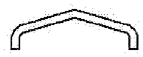
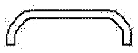
- 1plates
- 2lower elastic plate
- 3pressing plate
- 10lower elastic plates
- 11respective cutting edges
- 12lower elastic plate
- 14support shaft
- 15pressing plate
Abstract
A nail clipper includes upper and lower elastic plates which have respective cutting edges formed on respective front ends thereof and are connected with each other at rear ends thereof, a support shaft which passes through front end portions of the upper and lower elastic plates, and a pressing plate which is coupled to the support shaft at a front end thereof. One or more of the upper, lower and pressing plates are formed to have arc-shaped widthwise cross-sections.
Description
TECHNICAL FIELD
[0001] The present disclosure relates to a nail clipper with light weight and excellent strength.
BACKGROUND ART
[0002] Referring to FIG. 1 , a conventional nail clipper is composed of an upper elastic plate 1 , a lower elastic plate 2 , and a pressing plate 3 . These plates 1 , 2 and 3 are made of steel plates.
[0003] The upper and lower elastic plates 1 and 2 are required to have adequate elasticity, and the pressing plate 3 is required to sustain so as to not yield the force applied thereto. To satisfy the requirements, the respective component plates must have appropriate thicknesses. Accordingly, in the conventional nail clipper, a substantial amount of a material therefor is needed and a transportation cost thereof is significant due to the weight of the material.
[0004] The above information disclosed in this Background Art section is only for enhancement of understanding of the background of the invention and therefore it may contain information that does not form the prior art that is already known in this country to a person of ordinary skill in the art.
SUMMARY
[0005] One of the objects of the present invention is to provide a nail clipper in which upper and lower elastic plates and a pressing plate have lighter weights compared to the conventional art.
[0006] Another object is to provide a nail clipper in which upper and lower elastic plates and a pressing plate show excellent strengths.
[0007] In one aspect, the present invention provides a nail clipper including upper and lower elastic plates which have respective cutting edges formed on front ends thereof and are connected with each other at rear ends thereof, a support shaft which passes through front end portions of the upper and lower elastic plates, and a pressing plate which is coupled to the support shaft at a front end thereof. At least one of the upper plate, the lower plate and the pressing plate is formed to have an arc-shaped widthwise cross-section, thereby making it possible to reduce the thickness of the upper and lower elastic plates and the pressing plate.
[0008] Preferably, the rear ends of the upper and lower elastic plates may be integrally connected with each other by a bent part.
[0009] Other aspects and preferred embodiments of the invention are discussed infra.
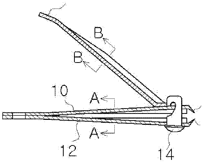
BRIEF DESCRIPTION OF THE DRAWINGS
[0010] The above and other objects, features and other advantages of the present invention will be more clearly understood from the following detailed description taken in conjunction with the accompanying drawings, in which:
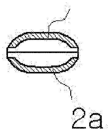
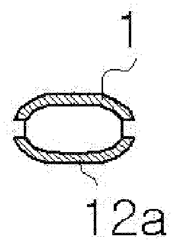
[0011] FIG. 1 is a perspective view illustrating a conventional nail clipper;
[0012] FIG. 2 is a lengthwise sectional view illustrating a nail clipper in accordance with one embodiment of the present invention;
[0013] FIG. 3 is a sectional view taken along the line A-A of FIG. 2 ;
[0014] FIG. 4 is a sectional view taken along the line B-B of FIG. 2 ;
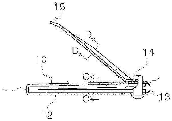
[0015] FIG. 5 is a lengthwise sectional view illustrating a nail clipper in accordance with another embodiment of the present invention;
[0016] FIG. 6 is a sectional view taken along the line C-C of FIG. 5 ;
[0017] FIG. 7 is a sectional view taken along the line D-D of FIG. 5 ;
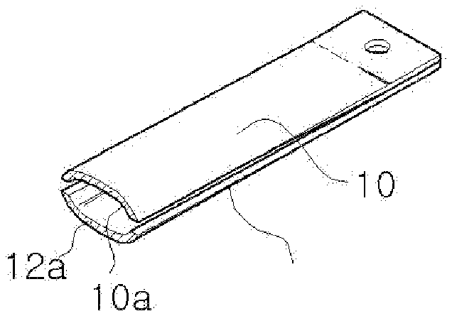
[0018] FIG. 8 is a perspective view of the upper and lower elastic plates of the nail clipper of FIG. 2 ;
[0019] FIG. 9 is a perspective view of FIG. 2 ;
[0020] FIG. 10 is a perspective view of the upper and lower elastic plates of the nail clipper of FIG. 5 ; and
[0021] FIGS. 11( a ) through 11 ( f ) are views illustrating exemplary sectional shapes of the nail clipper according to the present invention.
DETAILED DESCRIPTION
[0022] Reference will now be made in greater detail to preferred embodiments of the invention, examples of which are illustrated in the accompanying drawings. Wherever possible, the same reference numerals will be used throughout the drawings and the description to refer to the same or like parts.
[0023] FIGS. 2 through 4 are sectional views illustrating a nail clipper according to one embodiment of the present invention. The nail clipper includes a upper elastic plate 10 , a lower elastic plate, a support shaft 14 , and a pressing plate 15 .
[0024] The upper and lower elastic plates 10 and 12 have respective cutting edges 11 and 13 formed on the respective front ends thereof and are joined with each other at the rear ends thereof through welding. The support shaft 14 passes through the front end portions of the upper and lower elastic plates 10 and 12 . The pressing plate 15 is coupled to the support shaft 14 at the front end thereof.
[0025] In the nail clipper, the upper and lower elastic plates 10 and 12 are formed to have smaller thickness than those of the conventional nail clipper. The upper and lower elastic plates 10 and 12 are formed to have arc-shaped widthwise cross-sections 10 a and 12 a as shown in FIGS. 3 and 8 .
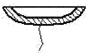
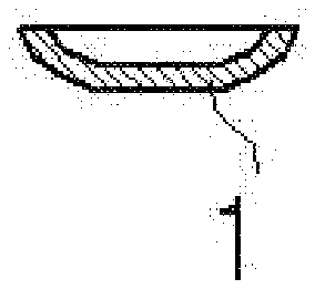
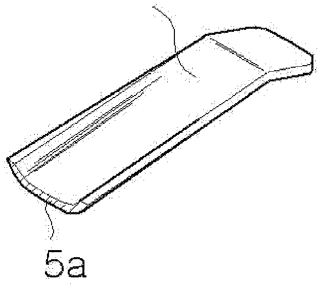
[0026] The pressing plate 15 is also formed to have smaller thickness than that of the conventional nail clipper and is formed to have an arc-shaped widthwise cross-section 15 a as shown in FIGS. 4 and 9 .
[0027] FIGS. 5 through 7 are sectional views illustrating a nail clipper according to another embodiment of the present invention. The nail clipper includes a upper elastic plate 10 , a lower elastic plate 12 , a support shaft 14 , and a pressing plate 15 .
[0028] The upper and lower elastic plates 10 and 12 have respective cutting edges 11 and 13 formed on the respective front ends thereof and are connected with each other at the rear ends thereof. The support shaft 14 passes through the front end portions of the upper and lower elastic plates 10 and 12 . The pressing plate 15 is coupled to the support shaft 14 at the front end thereof.
[0029] In the nail clipper, the upper and lower elastic plates 10 and 12 are formed to have smaller thickness than those of the conventional nail clipper. The upper and lower elastic plates 10 and 12 are formed to have arc-shaped widthwise cross-sections 10 a and 12 a as shown in FIGS. 6 and 10 .
[0030] The pressing plate 15 is also formed to have smaller thickness than that of the conventional nail clipper and is formed to have an arc-shaped widthwise cross-section 15 a as shown in FIG. 7 .
[0031] In this embodiment, the rear ends of the upper and lower elastic plates 10 and 12 are integrally connected with each other through a bent part 26 .
[0032] In the above embodiments, the arc-shaped cross-sections 10 a, 12 a and 15 a are formed to reinforce the bending stress resulting from the smaller thickness of the upper and lower elastic plates 10 and 12 and the pressing plate 15 .
[0033] In this regard, the upper and lower elastic plates 10 and 12 and the pressing plate 15 may have other sectional shapes as exemplified in FIGS. 11( a ) through 11 ( f ).
[0034] Accordingly, the present nail clippers can be reliably used without causing any problem associated with the conventional nail clipper. Further, since the upper and lower elastic plates are formed integrally with each other through the bent part, manufacturing process can be simplified. Also, since the cross-sections of the plates are arc-shaped, it is possible to reduce the thickness of the plates, thereby reducing manufacturing and transportation costs and overall weight of the nail clipper.
[0035] Although preferred embodiments of the present invention have been described for illustrative purposes, those skilled in the art will appreciate that various modifications, additions and substitutions are possible, without departing from the scope and spirit of the invention as disclosed in the accompanying claims.

