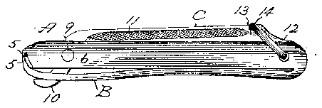
- 3l iyand
- 6turned-down flanges
- 8longitudinal slot
- 9pin
- 10short end
- 11grooved file
- 12pointed blade-like nail-cleaner
- 13transverse groove
- 14swinging bail
- 23central erforation 7 fi
Description
(No Model) J. D. 0. WENGER. FINGER NAIL CLIPPER.
No. 569,903. Patented 0013.20, 1896.
LUZ/755555 1/7 vE fim- GfuZiusD G 2002 ihvirnn ST TES JULIUS D. C. wnnenn, OF ANSONIA, CONNECTICUT, AssIeNoH'Toi-LEWIs 1 PATENT OFFICE.
coon AND CHAPEL s. CARTER, or SAME f LACE FlNG ER-NA'IL QLIPPER.
PECH'ICATZON forming part of Letters Ifatent No. 569,903," October 20, 1896.
Application filed March 2 1, 1896. Serial No. 584,242 (No model-l To aZZ whom it may concern.-
Be it known that I, JULIUS D. G. WENGER, a citizen of the United States, residing at Ansonia': in the county of New Haven and State 5 of Connecticut, have invented certain new and useful Improvements in FingerNail onppers, of which the following is a specification. My invention relates tov improvements in finger-nail clippers or cutters, and the main objects of my improvements are simplicity and economy in construction and general efliciency and convenience in use.
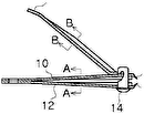
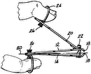
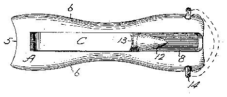
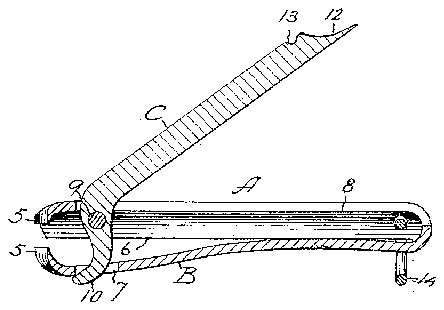
In the accompanying drawings, Figure l is a side elevation of my clipper with the lever I released. Fig. 2 is a plan view of the same.
' Fig. 3 is a central longitudinal section thereefi, and Fig. 4c is a side elevation with the lever confined for convenience of carrying or storage when not wanted for immediate use. My implement consists mainly of a rigid member A, a spring member l3, and an operating-lever C. The rigid and spring member are preferably formed from a single piece of sheet metal, swaged or struck up into form and doubled upon itself at their junction, which forms one end of the implement. The other end of these members are somewhat curved in planview and formed with cutting jaws 5, whose edges shut squarely against 0 each other, as in ordinary cutting-pliers, only lhc edges are curved in plan view instead of being straight. The member A is made practically rigid by providing its side edges with turned-down flanges 6, While the spring 111cm- 3 5 her 13 is left comparatively flat in cross section. Near the cutting end of the spring member I form a central erforation 7 Fi 23, and in the middle of the rigid member I form a longitudinal slot 8, Within which 1 4o pivot the operating-leverO on any suitable fulcrum-as, for example, the pin 9. The short end 10 of the lever C is, for a short-distance, substantially parallel to the body of said lever and extends down through the per- 5 foration 7 of the spring member. The tendcncy of said spring member is to open and throw the lever into the position shown in Figs. l iyand 3 whenever said lover is released. The said lever may be provided with files, nailecleanersbr 'any convenient tools. I prefer lofornra plain fiat filc on one edge and a grooved file 11, as shown, on the other edge. I have also shown said lever as pro: vided with a pointed blade-like nail-cleaner 12 and a transverse groove 13 near the end.
For convenience of carrying in a pocket or for compactness in form when not wanted for immediate use some means should be prolongitudinal slot out of the way and thereby holding the jaws in a nearly-closed position. I have illustrated the implement as provided is indicated in plan view by the broken lines in Fig. "2. \Vhen turned down, as shown by full lines in Figs. 1, 2, and 3, it will stay out of the way of the lever, but whendesired after depressing the lever the bail may be the outer side of the lever, as shown in Fig. l, thereby confining the lever until again wanted for use.
finger-nails, the lever is liberated, so that the jaws spring open. presented to the nail and the lever depressed between the cutting-jaws. The implement is then moved along and the operation .repeated.
By my improvements alight, neat, and efficient nail-clipper is produced at a small cost. The construction of the lever and jaws gives the spring member connected therewith by one end, coactingcutters on the disconnected ends of said members, and the operating-lover pivoted on the rigid member near the cutvided for holding the lever down within the turned over into the transverse groove 13 on The cutting ends are then fall within the spirit and scope of my inven-.
1. The combination of the rigid member;
with the swinging bail 14, the form of which I In order to use the implement for clipping to cut or clip on the portion of the nail lying a powerful purchase, and at the same time ters and haviifg a short end extended through a perforation iii the spring member, substantially as described and for the purpose specified.
2. The combination of the rigid member lon gitud i na] 1y s] )tted, the spring member connected therewit-L'by one end, coasting cutters at the disconneeted ends of said members, the operating-leverni voted to said rigid member,
and meansforoenfiningtheleverWhenturned no down into the-sh of the rigid member, sub stantiaily as described and for the purpose specified.
JULIUS D. O. YVENGER.
Witnesses ELIZABETH F. BENNETT, A. P. KIRKHAM
