

- 3figs
- 4figs
- 5i
- 6 marked
Description
Pategted lun'l7, I902. I
No. 702,5is.
H WILCOX RIGHT AND LEFT NAIL CLIPPER.
Application filed Oct. 19, 1901.)
(No Model.)
g g at a NDRHIS PCYLRS CG. PHQTOJJTAO WAENIN TO D C I UNITED STATES PATE T DF-FIGE.
HENRY WILCOX, OF' NEWARK, NEW JERSEY.
RIGHT AND LEFT NAIL-CLIPPER.
3PECIFIGATION formingpart of Letters Patent No. 702,516, dated June 17, 1902.
Application filed October 19, 1901'. Serial No. 79,196. (No model.)
To CLZZ whont it may concern:
Be it known that I, HENRY WILCOX, a citizen of the United States, residing at 22 Court street,'Newark, county of Essex, State of New Jersey, have invented certain new and useful Improvements in Right and Left Nail-Clippers, fully described and represented in the following specification and the accompanying drawings, forming a part of the same.
The object of this invention is to furnish, a nail-clipper with two cutting-faces arranged at the right and left sides of a central point,
so that when applied to the finger-nail it is adapted to trim the right and left sides of the nail with very little change of posit-ion on the part of the cutter or the hand which holds the same. These right and left cutting-faces are curvedto conform to the prevailing shape of the finger-nail and are formed upon levers, which are stamped separately from sheet metal and joined by a pivot close to the cutting-faces. The levers which project in the rear of the pivot are roughened to prevent slipping when held in the fingers and afford avery considerable leverage in closing the jaws, so that the nail is cut with great'ease and quickness. Each lever is formed in part of a flat plate and in part of flanges bent downward from the edges of the' plate, one
set of flanges being-fitted within the other and a rivet extended through bothto forma joint for the levers. One of the levers is furnished with a hinged file, which maybe folded upon the bottom of the'clipper, and the outer side of such file furnishes a rough surface to prevent the clipper from slipping when held in the fingers. A spring is inserted between the jaws to hold them normally separated. A sliding catch is extended from the plate of the upper jaw and arranged to engage the upper plate of the lower jaw to lock the jaws together when the implement'isnot required for use.
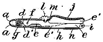
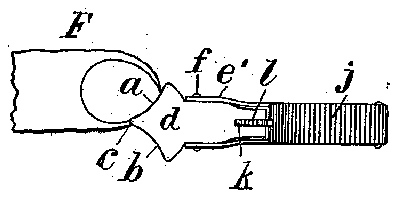
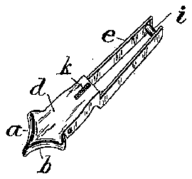
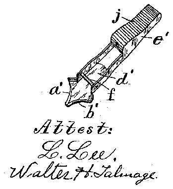
In the drawings, Figure 1 is a side elevation of the clipper with the jaws separated. Fig. 2 is a longitudinal section of the clipper with the jaws closed. Fig. 3 shows the top side of the clipper, and 4 the bottom side.
In Figs. 1 and 4 the file" is turned outwardly as would be necessary when required for smoothing the finger-nails. Fig. 5 is a perspective view of the lever carrying the lower jaw viewed from the upper side, and Fig. 6
a perspective view of the lever carrying the 2 upper jaw viewed from the upper side.
a and I) represent the right and left hand cutting-faces of the upper jaw formed at an angle of about ninety degrees to one another and joined at the forward apex c. The lower jaw is formed with corresponding cuttingt'aces a and b. The upper and lower jaws are formed, respectively, upon nearly flat plates 01 and (1, such plates beingprovided, respectively, with flanges at the edges, (marked 6 and e.) The flanges of one jaw are made to lie between those of theother jaw, as shown in Figs 3 and 4, and are connected bya pivot f at the rear of the cutting-faces. A spring g is inserted-within the jaws at the forward side of the pivot to normally separate the jaws. The flanges e of the npperjaw extend backwardly beyond the plate d, and a file h is hinged to their rear ends by rivet i, which permits the'file to be extended from the rear of the lever, as shown in Figs. 1 and 4, or
folded upon the lower face, as shown in Fig. 2. I
A finger-piece j is soldered to the flanges e, which are extended backward from the plate d of the lower jaw, and as the flanges of the upper and lower levers are crossed at the pivot such finger-piece lies upon the top side of the lever and is roughened transversely, V
as shown in Fig. 3, to prevent it from slipping when held in the fingers. Aslot kis formed in the plate (1 and a sliding catch Z is fitted to such slot and to a notch m, formed in the forward end of the finger-piecej to hold the jaws closed, as shown in Fig. 2, when the clipper is not required for use. The side of the file which is outward when it is folded upon the flanges e is'formed with serrations n opposite to the roughened finger-piecej,
The essential feature of my invention is the provision of the clipper with two cutting-faces arranged at the right and left sides of a central point, so that they are adapted to trim the right andleft sides of the nail with very little change of position on the part of the cutter. My invention also includes the special construction by which each of the levers is formed with a sheet-metal body-plate d or (1, having the integral side flanges e or c with the jaws at their forward ends and the flanges provided in the roar of the pivot with finger-pieces, by which they are held and pressed together. lhesurfaceotthefile which is used for smoothing the nails lies next the body of the clipper when it is turned inwardly, as shown in Fig. 2, and the roughened finger-seat n then lies upon the outside. It is immaterial whether such fingerseat is formed upon the hinged file or upon' a piece of metal soldered to the flangese in the same manner that the finger-piece j is soldered to the flanges e. I have termed a and b the cutting-faces of the upper jaw; but the clipper may be used with either side uppermost with the same convenience.
Having thus set forth the nature of the invention, what is claimed herein is 1. A nail-clipper having two lovers formed each with a sheet-metal body-plate having integral side flanges, and having jaws at their forward ends, a pivot extended through the flanges adjacent to the jaws, and a spring to hold the jaws normally separated.
2. A nail-clipper having two levers formed each with a flat plate and side flanges, and having jaws at their forward ends, a pivot extended through the flanges adjacent to the jaws, a spring to hold the jaws normally separated, and the side flanges of one lever arranged to contact with the plate of the opposite lever to limit the separation of the aws.
3. A nail-clipper having two levers formed each with a sheet-metal body-plate having integral side flanges, and having jaws at their forward ends, a pivot extended through the flanges adjacent to the jaws, and a roughened finger-piece supported upon the flanges of each lever in the rear of the pivot.
i. A nail'clipper having two levers formed each with a sheet-metal body-plate having integral side flanges, and having jaws at their forward ends, a pivot extended through the flanges adjacent to the jaws, a roughened finger-piece supported upon the flanges of each lever in the rear of the pivot, and a spiral spring inserted within the jaws to hold them normally separated. I 5. A nail-clipper having two levers formed l each with a sheet-metal body-plate having integral side flanges, and having jaws at their forward ends, a pivot extended through the flanges adjacent to the jaws, a spiral spring inserted within the jaws to hold them normallyseparated, andacatch to lock the levers together and hold the jaws closed when desired.
6. A nail-clipper having two levers formed each with a sheet-metal body-plate havingintegral side flanges, and having jaws at their forward ends, a pivot extended through the flanges adjacent to the jaws, a roughened finger-piece supported upon the flanges of each lever in the rear of the pivot, a spring to hold the jaws normally separated, and a catch arranged to slide upon the plate of the upper jaw and engage the finger-piece upon the opposed lever to hold the jaws normally closed.
7. A nail-clipper having two levers formed each with a sheet-metal body-plate having integral side flanges, and having jaws at their forward ends, a pivot extended through the flanges adjacent to the jaws, a spring to hold the jaws normally separated, a finger-piece attached to the flanges of the lever carrying the lower jaw, and a file hinged to the lever of the upper jaw and roughened to form an opposed finger-piece, substantially as herein shown and described.
8. A nail-clipper having two curved cuttingfaces arranged respectively at the right and left sides of a central point, and adapted to trim the right and left sides of the finger-nail with very little change of position on the part of the body of the cutter.
0. Anail-clipperhavingtwo curved cuttingfaces arranged respectively at the right and left sides of a central point, and finger-levers carrying jaws forming such cutting-faces and jointed together by a pivot adjacent to such cutters, and projected backward from such pivot.
10. A nail-clipper having two curved cutting-faces arranged respectively at the right and left sides of a central point, finger-levers formed each with a flat face and side flanges and provided with the jaws forming such cut ting-faces, a pivot extending through the flanges adjacent to the jaws, a spring to hold the jaws normally separated, an d a roughened finger-piece supported upon the flanges of each lever in the rear of the pivot.
In testimony whereof I have hereunto set my hand in the presence of two subscribing witnesses.
HENRY WILCOX. lVitnesses:
THOMAS S. CRANE, L. IJEE.


