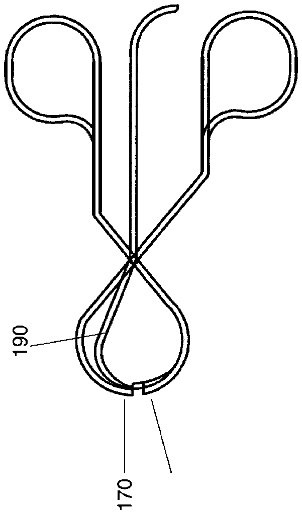
- 10first leg
- 60provisional patent application
- 100clipper
- 110cutting legs
- 115first finger controller
- 120gripping edge
- 150second leg
- 165second finger controller
- 170receiving edge
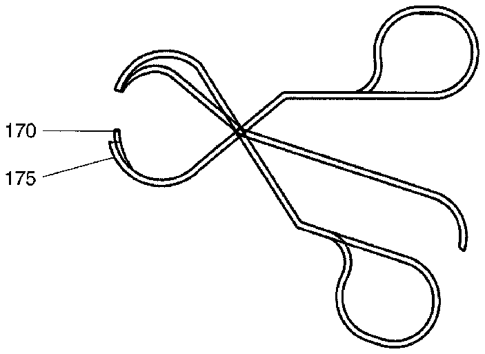
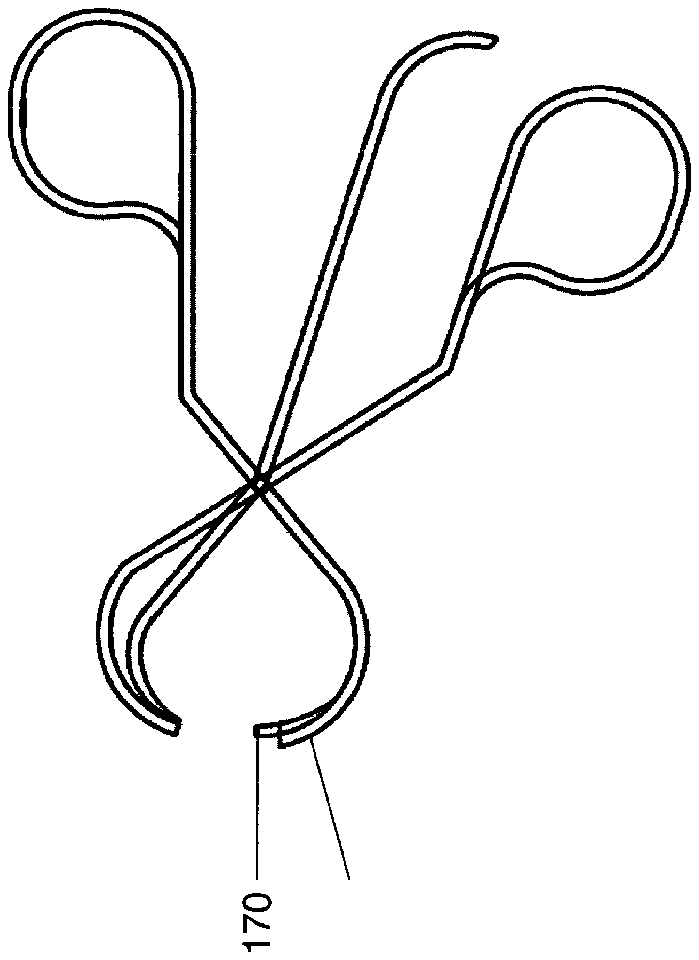
- 175holding edge
- 180cutting leg
- 185third finger controller
- 190cutting edge
- 199rotation point
Abstract
A nail clipper includes a first leg including a gripping edge and a second leg including a receiving edge and a holding edge, wherein the holding edge is configured to mate with the gripping edge. The clipper further includes a cutting leg including a cutting edge, wherein the first, second and cutting legs are each rotatably attached to the others at a single rotation axis.
Description
PRIORITY CLAIM
[0001] This application claims priority to U.S. Provisional Patent Application 60/572,424 filed May 19, 2004, the entirety of which is incorporated by reference.
FIELD OF THE INVENTION
[0002] This invention generally relates to the art of clippers and more specifically, to a clipper including multiple legs.
BACKGROUND OF THE INVENTION
[0003] Cutting finger and toe nails is often difficult, and may be more difficult with unwilling nails. For example, babies often find nail cutting unpleasant and squirm—generally making nail cutting more difficult and thus more unpleasant for the baby and the nail cutter.
[0004] The present invention advances the art.
BRIEF SUMMARY OF THE INVENTION
[0005] One aspect of the invention provides a nail clipper including a first leg including a lower portion and an upper portion opposite the lower portion. The first leg includes a first finger controller disposed at the lower portion and a gripping edge disposed at the upper portion. The nail clipper further includes a second leg including a first portion and a second portion opposite the first portion, the second leg including a second finger controller at the first portion and a receiving edge and a holding edge at the second portion, the holding edge configured to mate with the gripping edge. The clipper further includes a cutting leg including a third finger controller disposed at a fifth end opposite a cutting edge disposed at a sixth end of the cutting leg, wherein the first, second and cutting legs are each rotatably attached to the others at a single rotation axis.
[0006] The foregoing and other features and advantages of the invention will become further apparent from the following detailed description of the presently preferred embodiments, read in conjunction with the accompanying drawings. The detailed description and drawings are merely illustrative of the invention rather than limiting, the scope of the invention being defined by the appended claims and equivalents thereof.
BRIEF DESCRIPTION OF THE SEVERAL VIEWS OF THE DRAWINGS
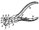
[0007] FIG. 1 illustrates one aspect of a nail clipper in accordance with one aspect of the invention; and
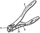
[0008] FIG. 2 illustrates a second aspect of a nail clipper in accordance with one aspect of the invention.
DETAILED DESCRIPTION
[0009] FIG. 1 illustrates one embodiment of a nail clipper 100 in accordance with one aspect of the invention. Clipper 100 is illustrated in an open configuration in FIG. 1 and a closed configuration in FIG. 2 , and therefore like numbers in each FIG. indicates like structures.
[0010] Clipper 100 includes first leg 110 , second leg 150 , and cutting leg 180 . In one embodiment, first leg 10 includes first finger controller 115 disposed opposite a gripping edge 120 . Second leg 150 includes receiving edge 170 and a holding edge 175 In one embodiment, second leg 150 includes a second finger controller 165 opposite the receiving edge 170 and holding edge 175 . Cutting leg 180 includes cutting edge 190 . In one embodiment, cutting leg 180 includes a third finger controller 185 disposed opposite the cutting edge 190 .
[0011] First, second and cutting legs 110 , 150 , and 180 are attached to each other at rotation point 199 . Rotation point 199 is configured such that each leg may rotate freely respective of the other legs between an open position (as illustrated in FIG. 1 ) and a closed position (as illustrated in FIG. 2 below). In one embodiment, each of the first, second and cutting legs 110 , 150 , and 180 are independently rotatable respective of the others.
[0012] Each structure disclosed herein is comprised of an appropriate, sufficiently rigid material. In one embodiment, each structure comprises a metal, such as, for example, stainless steel. Cutting edge 190 is configured to create a nip and, in one embodiment, comprises a sharp edge configured to be sufficiently sharp to cut a nail. The sharpness of cutting edge may vary as would be desirable for a particular application.
[0013] Those of skill in the art will readily recognize that the apparatus disclosed allows for a finger to be gripped between gripping edge 120 and holding edge 175 between an end of a nail and the first phalange. Gripping the finger in such a fashion allows for partial immobilization of the digit. The device is positioned on the finger such that the finger is gripped to place the targeted nail between the receiving edge 170 and cutting edge 190 when the apparatus is rotated between an open and a closed position, enabling the operator to reduce the mobility of the digit while cutting the nail. It should be noted that the gap between gripping edge 120 and holding edge 175 , upon closing the apparatus, will result in gripping the finger and the gap may be larger to accommodate a larger portion of the finger, or smaller. For example, if the apparatus during operation is to grip a finger nail, gripping edge 120 and holding edge 175 will be in close proximity, although not in contact. In another example, if the apparatus is gripping a knuckle, gripping edge 120 and holding edge 175 will be relatively distant.
[0014] The present invention may be embodied in other specific forms without departing from its spirit or essential characteristics. The described embodiments are to be considered in all respects only as illustrative and not restrictive.
