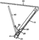
- 1comprising
- 12housing means
- 14cover means
- 16side walls
- 18side walls
- 20base member
- 22projecting tab
- 26downwardly extending side walls
- 28downwardly extending side walls
- 30top member
- 32front wall
- 34rear wall
- 38lower jaw member
- 40upper jaw member
- 42cutting surface
- 43opening
- 44cutting surface
- 46enlarged midsections
- 52pin
- 54elongated slots
- 55opening
- 56enlarged sections
- 60shoulders
- 394ted bythe examiner united states patents
- 727ted bythe examiner united states patents
Description
T. S. BOWERS NAIL CLIPPER May 2, 1967 Filed July 5, 1966 FIG.
FIG. 4
FIG.6
FIG. 5
FIG. 8
THOMAS m i PWM ATTOR N EY United States Patent O NAIL CLIPPER Thomas S. Bowers, 3544 Grantley Road,
Toledo, Ohio 436116 Filed `Iuly S, 1966, Ser. No. 562,733 Claims. (Cl. 3ft-28) v This invention relates generally to cutting devices and, more particularly, to a clipper for cutting fingernails and the like. Many types and variations of nail clippers are known in the prior art. Among these are clippers having a lever member which is movable from an operative position to an inoperative position for convenience of carriage. In addition to the now conventional clipper where the lever member may be pivoted and folded to a compact position, the prior art includes clippers having a generally channel shaped construction with a lever member cooperating with the channel shaped construction to perform a cutting operation in one position while being movable to a second closed position for easy carriage. These prior art devices, however, have been somewhat awkward to operate. Accordingly, an object of this invention is to provide nail clippers W 'ch are simple and easy to operate;
Another object of this invention is to provide nail clipperswhich are easily and conveniently stored for carriage;
A further object of this invention is to provide nail clippers in which the cover or lever member therefor is moved from a first position to a second position upon normal movement of the thumb when the nail clipper is placed upon the lingers of the hand of the user'and is also conveniently and easily returned to its rst position, again with a normal movement of the thumb of the users hand; and
A still further object of this invention is to provide nail clippers wherein the housing is of simple construction and in which the cover member of the clipper completes and complements the simple housing design to form a suitable uniform construction (without protrusions) for carriage by the user.
In one preferred embodiment of this invention the nail clipper is provided with a housing member within which is nestled a cover means. The cover means is positioned for movement such that when the nail clipper is placed on the fingers of the hand, movement of the thumb away from the user in a normal manner to apply pressure to the cover member causes sliding movement of the cover member to a closed position for carriage. Also, upon normal movement of the thumb to apply pressure to the front of the cover member, the cover member is slid rearwardly to an open operating position in which the rear of the cover swings upwardly with such movement being accommodated by the position of the hand in applying the opening pressure.
These and other objects and advantages of this invention will become apparent upon consideration of the detailed specification when taken in connection with the accompanying drawings wherein:
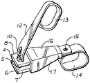
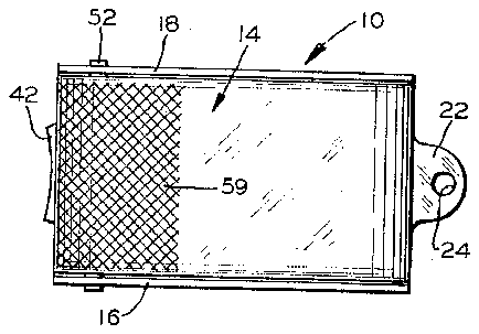
FIG. 1 is a plan view of the nail clipper embodying this invention;
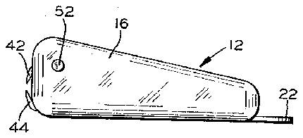
r EIG. 2 is a side elevation view of the nail clipper shown in FIG. 1;
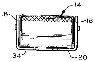
FIG. 3 is a rear elevation view of the nail clipper shown in FIG. 1;
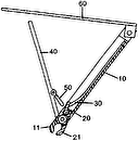
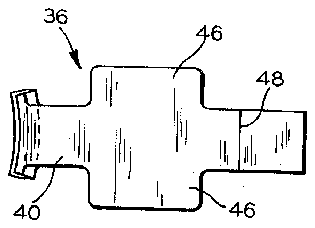
FIG. 4 is a plan view of the cutting device used in the nail clipper shown in FIG. l;
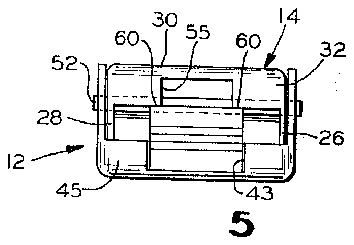
FIG. 5 is a front elevation shown in FIG. 1;
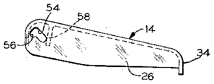
FIG. 6 is a side elevation View of the cover member used in the nail clipper shown in FIG. 1;
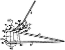
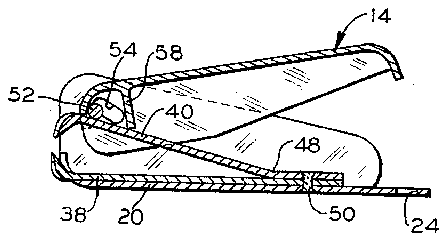
FIG. 7 is a longitudinal section View of the nail clipper View of the nail clipper `longitudinal movement to a 3,316,532 Patented May 2, 1967 of this invention illustrating the clipper in the closed or carriage position; and
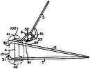
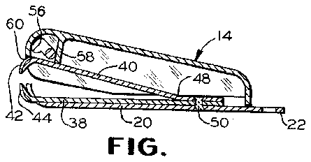
FIG. 8 is another longitudinal section view of the nail clipper utilizing this invention showing the clipper in the open or operating position.
Referring now more particularly to the drawings, the cutting device or nail clipper, illustrated generally by the numeral 1G, comprises a housing means 12 and a cover means 14. The housing means 12 includes a pair of upwardly extending parallel side walls 16 and 18 integrally connected together by a horizontally extending base member 20. For convenience of design and appearance, the corners of the housing member are rounded and the side walls 16 and 18 are of progressively reduced height when proceeding from the forward end of the side wall to the rearward end thereof. The base member 20 is of the same length as the side walls of the housing but is provided at the central portion of its rearward end with a projecting tab 22 which is suitably pierced at 24 for the purpose of accommodating a key chain or similar device for carriage of the nail clipper.
The cover means 14 comprises a pair of downwardly extending side walls 26 and 28 connected at their upper extremities by a top member 30. Also, the forward end of the cover means is provided with front wall 32 and the rearward end of the cover means is provided with a rear wall 34. The dimensions of the cover means are slightly less than the dimensions of the housing means so that the cover means is conveniently accommodated between the side walls of the housing member and the lines of the cover member complement the lines of the housing member so that protrusions do not exist.
A cutting device indicated generally at 36 is carried by the base member 20 of the housing means 12. The cutting device includes a lower jaw member 38 and an upper jaw member 40 of generally similar configuration and which cooperate for performing the cutting operation. The lower cutting jaw is positioned on the base member 20 with the upwardly projecting cutting surface 44 protruding slightly beyond an opening 43 the front surface 45 of the housing means 12 and the cover means 14. The Iupper jaw member 40 is positioned on top of the lower jaw member 38 and has a downwardly projecting cutting surface 42 which cooperates with the cutting surface 44. The jaw members 38 and lil are of any general configuration and are here shown (FIG. 4) as including longitudinally extending blades with enlarged midsections 46. The upper and lower jaw members differ slightly in configuration in that the upper jaw member 40 is angularly deformed adjacent the rearward end thereof at 48 so that the forward end of the upper jaw member is displaced upwardly with respect to the lower jaw member 38. The jaw members are secured at their rearward end to each other and to the base member 20 by a tack weld indicated at Si) so that the cutting surface 42 of the upper jaw mem-ber is suspended for resilient movement to and from its cooperating position with the lower jaw member.
A pin S2 extends through the forward portion of the upwardly extending side walls 16 and 18 of the housing 12 (and is suitably secured thereto) and also through the forward portion of the downwardly extending side walls 26 and 28 of the cover means 14 to mount the cover means 14 with respect to the housing 12.
Means is provided to mount the cover means 14 for plurality of positions with respect to the housing 12. More particularly, the side walls 26 and 28 of the cover means 14 are provided with elongated slots 54 which extend at an angle of approximately 45 with respect to the top surface of the cover means 14 and in which is received the pin 52.
The height of the slots S4 is substantially similar in size to the diameter of the pin 52 and the slots have enlarged sections 56 at the forward ends thereof which provide an indexing means for the pin 52. Accordingly, it is apparent that the cover means 14 may move longitudinally with respect to the housing means 12 as the pin 52 moves from one end of the elongated slots 54 to the other end thereof.
Cam means is provided on the cover means 14 in the form of a downwardly projecting rib 58 which extends across the forward end of the cover means 14. Since the slots 54 extend at an angle with respect to the top of the cover means 14, rearward movement of the cover means causes the pin to move forwardly in the slot 54 tending to move the forward end of the cover means 14 downwardly. Downward movement of the forward end of the cover means 14 is accommodated by an opening 55 forming in the front wall 32 of the cover means to enable the upper jaw member 40 to remain in its open position. During this movement, the cam means 58 rides on top of the upper jaw member 40 and forces the rearward end of the cover means 14 to an upright position extending angularly with respect to the housing means 12 (see FIG. 8). At the limit of the rearward movement of the cover means 14 the indexing means S6 of the cover means 14 receives the pin 52 and forms a pivot point for the cover means 14.
Thus, when the nail clipper is placed on the fingers of the hand and the thumb is pressed against the upwardly extending cover means 14, resultant movement of the ngers and the thumb toward each other causes the cam means to engage the resiliently suspended upper jaw member 40 and press the same downwardly so that a fingernail or the like positioned between the cutting surfaces 42 and 44 is suitably sheared. Upon release of the thumb pressure, the resiliency of the upper jaw member pivots the cover means 14 in a counterclockwise direction about the pin 52 so that the nail clipper is again ready to perform another cutting operation.
To move the cover means 14 to its forward position so that the nail clipper is of uniform compact construction for carriage, with the nail clipper placed on the fingers of the hand the thumb is moved forwardly in the normal cradle-like sliding motion along a serrated surface S9 provided on the forward portion of the cover means to slide the cover means 14 forwardly so that the pin 52 is located at the rear of the elongated slots 54. During such movement, since the slots are angularly placed with respect to the top of the cover means 14, the forward end of the cover means 14 moves upwardly while the rearward end thereof pivots downwardly so that the rearward portion is positioned adjacent the base mem-ber 20 of the housing means 12. This pivoted movement of the cover means 14 is facilitated by the forward end of the upper jaw member 40 (adjacent cutting surface 42) engaging abutment means in the form of shoulders 60 provided by relieve portions adjacent the front wall opening 55 of the cover means 14. The resiliency of the upper jaw member tends to pivot the cover means 14 in a clockwise direction about the pin 52 to bias cover means 14 to such a position insuring safe carriage.
From the foregoing it is apparent that a nail clipper has been provided which is conveniently operated to place the nail clipper in its operating position or its compact carriage position without awkward pivoting of the cutting lever, which is common in conventional nail clippers and in a positive pleasing manner. Furthermore, a nail clipper has been provided which is of uniform compact construction, so that it is not subject to damage and is easily carried.
While only a single embodiment of this invention has been shown and described, it is apparent that there may be changes in structure and operation without departing from the scope of this invention as defined by the appended claims.
What is claimed is:
1. A nail clipper comprising:
(a) a housing member including a pair of upwardly extending side walls connected by a base member,
(b) cutting means carried by the base of said housing member and comprising (1) an upper jaw member and a lower jaw member,
(2) said jaw members being joined together adjacent one of their ends with the other ends of said jaw members being resiliently movable relative to each other,
(c) cover means adapted to be nestled between the side walls of said housing means and comprising (1) a pair of downwardly extending side walls connected together by a top member,
(2) said side walls of said cover means being provided with elongated slots extending at an angle with respect to said top member,
(d) pin means extending through the side Walls of said housing member and said elongated slots of said cover means whereby said cover means can be moved forwardly so that said pin means is at the rear of said elongated slot or rearwardly so that said pin means is at the front of said elongated slot,
(e) cam means on said cover means engaging said upper jaw member for moving the same to perform a cutting operation when said cover means is in its rearward position,
(f) the angle of said elongated slot in said cover means permitting said cover means to be easily slid forwardly to a storage position with the natural movement oft he thumb of the user when the nail clipper is resting on the lingers of the hand of the user and permitting said cover means to be easily slid rearwardly to an operating position by slight and natural pressure of the thumb of the user on the forward portion of said cover means, the movement of the thumb permitting the rear of the cover means to swing upwardly.
2. The nail clipper of claim 1 having abutment means on the forward portion of said cover means and engaged by said upper jaw member when said cover means is in its forward position to resiliently bias said cover means to a position nestled between the side walls of said housing means.
3. The nail clipper of claim 1 wherein said cover means is provided with a front wall and said front wall forms an opening into which the upper jaw member projects when said cover means is moved to its rearward position.
4. The nail clipper of claim 1 wherein said elongated slots in the side walls of said cover means are provided with index means at the forward end of said slots so that said cover means is positively positioned with respect to said pin means when said cover means is moved to its rearward position.
5. The nail clipper of claim 1 wherein said side walls of said housing means are of plain solid construction with pin means being secured thereto.
References Cited bythe Examiner UNITED STATES PATENTS 1,394,727 10/1921 Gronbech 30-28 2,179,435 11/1939 Smith 30-28 WILLIAM FELDMAN, Primary Examiner.
G. WEIDENFELD, Assistant Examiner.


