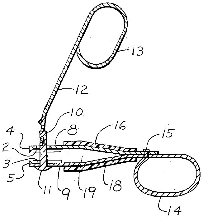
- 1receptacle
- 2left cutting jaws
- 3left cutting jaws
- 4opposite end contains front cutting jaws
- 5opposite end contains front cutting jaws
- 6right cutting jaws
- 7right cutting jaws
- 10operating arm rivet
- 11operating arm rivet
- 12operating arm
- 13formed handles
- 14formed handles
- 15rivet
- 17two side walls
- 18bottom wall
- 19two side walls
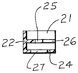
- 20removable front lid
- 21two lid side walls
- 22lid front wall
- 23two lid side walls
- 24lid bottom
- 25operating arm rivet catch opening
- 26slotted insert
- 27bottom operating arm rivet opening
Abstract
An improved nail clipper which contains upper and lower handles to facilitate holding the unit and maintaining it in the desired position. Comprising cutting jaws in three sides to allow nail clipping from different and more convenient angles. Also a clipping receptacle with removable lid which surrounds the unit and holds the clippings produced, therein.
Description
BACKGROUND OF THE INVENTION
This invention relates generally to nail clippers with receptacles and a front lid and in particular to a new and improved nail clipper which contains cutting jaws on three sides to obtain the desired clipping angle, having handles for convenience and to maintain a more secure grip on the unit. Also included is a removable front lid to hold waste clippings, therein.
A case with closeable lid for a nail clip is disclosed and claimed in U.S. Pat. No. 3,943,948 issued Mar. 16, 1976 to the inventor of the present invention.
Some problems and limitations which this invention solves are:
First, the clipper can now be placed at different desired angles for clipping the nails.
Secondly, the upper and lower handles make holding the nail clipper easier and more secure.
Thirdly, the clipping receptacle with removable front lid will prevent unwanted waste clippings from being dispersed in the surrounding environment.
Fourthly, the removable front lid can fit between the cutting jaws, engage the nail clipper operating arm rivet to allow the front lid to be held in position and effectively cover the cutting jaws.
Other uses and benefits will become apparent during this disclosure.
SUMMARY OF THE INVENTION
This invention is a new improved nail clipper with clipping receptacle and removable front lid which can be made of any material desired. However, the nail clipper members, operating arm rivet, and operating arm should preferably be made from a hard resilient material such as spring steel.
The nail clipper is comprised of cutting jaws on three sides of its opposite end, whose movement is controlled by an operating arm which is attached to an operating arm rivet passing through aligned openings in the nail clipper members.
Handles placed at the end of the nail clipper members (the end opposite the cutting jaws) and at the end of the operating arm (end which does not contain the operating arm rivet) provide a secure hold for the fingers of the operator.
The clipping receptacle surrounds the nail clipper members preventing escape of waste clippings and the front closeable lid completes the enclosure.
The principle objective of this invention is to provide upper and lower handles to allow the nail clipper to be held more securely and conveniently during the nail clipping operation.
Secondly, side cutting jaws are included to allow the nail clipper to be placed at a more natural and convenient angle in respect to the nail, when the clipping operation is being carried out.
Thirdly, the nail clipper is provided with a clipping receptacle and removable front lid to hold nail clippings which would otherwise be randomly and haphazardly be dispersed into the surrounding environment.
These and other advantages of the invention will become apparent after a study of the drawing and after reviewing the written specification describing the preferred embodiment. Like numerals are employed to designate like parts throughout same.
BRIEF DESCRIPTION OF THE DRAWING
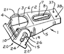
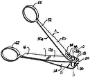
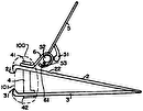
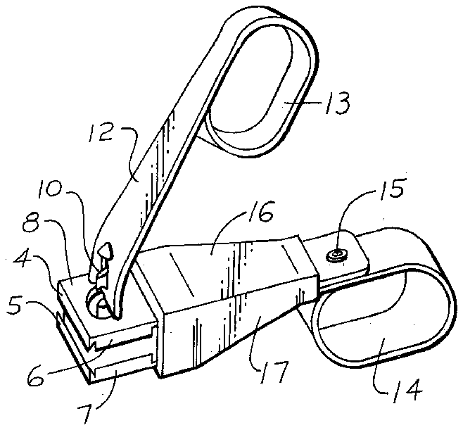
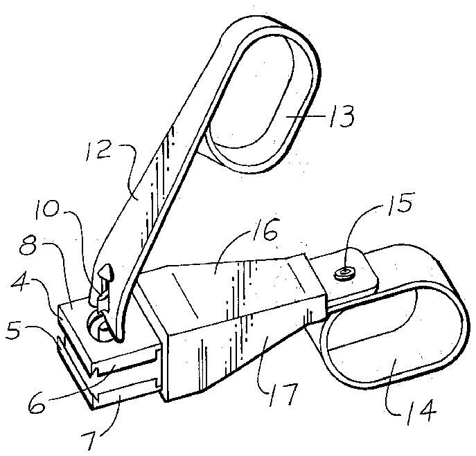
FIG. 1 is an isometric view of the new improved nail clipper, clipping receptacle and removable front lid.
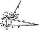
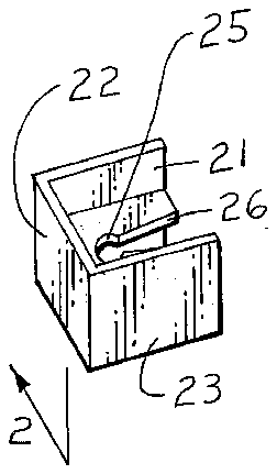
FIG. 2 is a cross sectional view of the improved nail clipper, clipping receptacle and removable front lid taken along lines 2--2 of FIG. 1.
DESCRIPTION OF THE PREFERRED EMBODIMENT
Referring to the drawing in general and particularly to FIG. 1 of the drawing, is shown the new improved nail clipper with a clipping receptacle depicted generally by the numeral 1 and a removable front lid shown generally by the numeral 20. The nail clipping receptacle and removable front lid can be formed of plastic or any other material desired. However, the nail clipper parts must be formed of a hard material and or resilient material, such as, spring steel or any material exhibiting such qualities.
The clipping receptacle 16-19 and or the removable front lid 20 may each be constructed in a one-piece configuration as can be seen from FIGS. 1 and 2 or may be constructed in more than one piece by providing manufactured joints where required.
The nail clipper may be constructed of strong resilient parts, such as, from spring steel, fastened and or combined as shown in FIGS. 1 and 2 of the drawing.
The nail clipper is comprised of upper nail clip member 8 and lower nail clip member 9 fastened at their one end by means of rivet 15 and or manufactured joints. At this same end and formed from the lower nail clip member 9 is a lower formed handle 14, see FIGS. 1 and 2.
The opposite end contains front cutting jaws 4 and 5, left cutting jaws 2 and 3 and right cutting jaws 6 and 7. They will allow the nail clipper and receptacle 1 to be held at a more convenient angle to facilitate the nail clipping operation. Also at this opposite end are placed two aligned openings through which is passed an operating arm rivet 10, attached to an operating arm 12 having an upper formed handle 13 at its end, see FIGS. 1 and 2.
The upper and lower formed handles 13 and 14 are so located that when in the non cutting or stored position, the formed handles 13 and 14 can be aligned to utilize the minimum amount of space possible. When in the cutting position, the operating arm 12 and the nail clipper members 8 and 9 with the clipping receptacle 16 through 19 will assume diverged position. Grasping the formed handles 13 and 14 will secure the fingers and hand hold on the nail clipper with clipping receptacle 1. Then manipulating action of the fingers using the formed handles 13 and 14 will be transmitted from the operating arm 12 to a raised portion on the operating arm which makes contact with the upper nail clip member 8 and will, in turn, result in the movement of the end containing the cutting jaws 2-7, see FIG. 2.
The nail clipping receptacle 16-19 contains top wall 16, bottom wall 18, and two side walls 17 and 19 in continuous relationship with each other with an opening running through the longitudinal portion and surrounding the nail clipper members 8 and 9. It is held in a fixed position by formed handle 14 acting as a stop. It then functions to contain waste clippings therein, see FIGS. 1 and 2.
A removable front lid 20 is also provided to complete the enclosure along with the clipping receptacle 16-19. The removable front lid 20 is provided with a lid front wall 22 and two lid side walls 21 and 23 in continuous relationship surrounding the cutting jaws 2-7 with slotted insert 26 to fit between them and operating arm rivet catch opening 25 to hold the removable front lid 20 in place. Lid bottom 24 contains a bottom operating arm rivet opening 27 to mate with the bottom of operating arm rivet 11 to form an additional catch. This completes the enclosure, see FIGS. 1 and 2.
It is to be understood that the aforementioned invention shown and described is to be taken as a preferred example of the same and that various changes relative to material, size, shape and arangement of parts may be resorted to without departing from the spirit of the invention and the subjoined claims.

