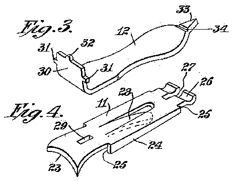
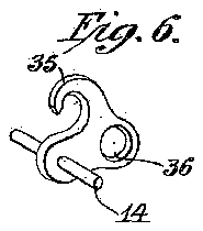
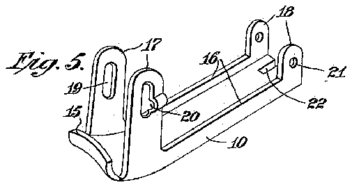
- 1clasp axle
- 6i
- 10member
- 11member
- 12finger lever
- 13clasp
- 14axle
- 15cutting jaw
- 16walls
- 17extended portions
- 18extended portions
- 19slots
- 20offset
- 21openings
- 22centrally located bifurcation
- 23cutting jaw
- 24side walls
- 25rearward shoulders
- 26bearing surfact
- 28tongue
- 29slot
- 30portion
- 32teat
- 33point
- 34groove
- 36opening
- 91patentgd
- 141axle
- 180be moved
Description
C. E. A. GRONBECH. NAIL CLIP. APPLICATION FILED MAY, 192
In ventor: Christ/an E. A .Gron bech y 9M K/ w Arty Patented Oct. 25, 1921,-
CHRISTIAN E. A. GRONBECH, OF KEENE, NEW HAMPSHIRE.
NAIL-CLIP.
To a/ll whom it may concern:
Be it known that I, CHRISTIAN E. A. GRoNBEoH, acitizen of the United States, residing at Keene,in.thecounty of Cheshire and State of New Hampshire, haveinvented certain new and useful Improvements in Nail-Clips, of which the following is a specification.
This invention relates to improvements in the construction of nail clips and more particularly to a means whereby the several elements constituting the entire device may beheld against dislocation from one another. 7
'In the construction of nail clips of this character, heretofore, difficulties have always been encountered, chiefly affecting the v derangement of the finger lever which op erates or depresses the upper cutting jaw, and withthis faulty construction in view I have provided a means whereby the finger lever is held against possible dislocation, except when a deliberate effort is made to separate the several members.
Therefore, an object of thisinvention'is to provide an efficiently operating device of this character, wherein the number of parts used is reduced to a minimum, thereby decreasing the cost of production and the liability of derangement.
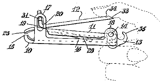
The invention consists in the structural features and combinations of parts herein after fully described with reference to the accompanying drawing, wherein Figure 1 is a side elevational view of the improved nail clip, showing the finger lever in partially raised position and the cutting jaws parted. V
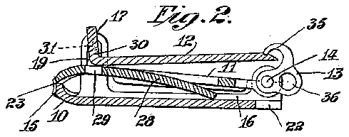
Fig. 2 is a substantially longitudinal sectional view through the nail clip with the finger lever in itsdepressed position and the cutting jaws in contact with each other.
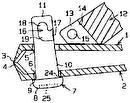
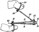
' Figs. 3, 4:, 5 and 6 are respectively perspective views.
Referring to the drawing, 10 and 11 denote the cutting elements of the instrument and 12 the finger lever, which are the principal parts of the nail clip comprising the invention. A pivoted clasp 13- carried by an axle 141 completes the catalogue of parts which go to make up the completed instrument.
One end of the member 10 is provided I Specification of Letters Patent. Patentgd ()91 25, 1921,
Application filedMay 17, 1921. v Serial No. 470,226.
with an upwardly turned concave cutting jaw 15 extending substantially across the width thereof. Longitudinally disposed upturned walls 16 carried by the. member 10 are extended at 17 and 18 respectively, considerably above their normal level and adjacent their ends. The extended portions 17 at the forward end of the member 10 are somewhat higher than that of the rearwardly located extended portions 18 and are provided with elongated openings or slots 19, one of said slots 19 having its rear wall outwardly offset at-20closely adjacent the lower portion of the slot. Suitable openings 21 inthe portions 18 establish bearings for the clasp axle 1 1. A centrally located bifurcation 22 is provided at the rear edge of the member 10 to accommodate the clasp 13 as the latter is moved arcuately.
' The positive cutting member 11, which is adapted to overlie the member 10 between the walls 16, is arched at its forward end and terminates in a concaved cutting jaw 28 adapted to meet the similar cutting jaw 15 of the member 10. Side walls 24: extending below the surface of the member 11 provide forward and rearward shoulders 25 which abut the inner edges of the extended portions 17 and 18 respectively. The opposite end of the. member 11 is semi-arcuately formed at 26 to underlie the clasp axle 14; and is bifurcated at'27 to accommodate the clasp 13 in its arcuate movement. A spring tongue 28 is cut'from the central portion of the member 11 and depressed downwardly at its free end. A rectangular slot 29 is stamped out of the portion of the member 11 between the cutting jaw 23 and closed end of the tongue 28.
. The third principal member comprises the finger lever 12 having a location in the assembly of the instrument above the member 11 as shown in Figs. 1 and 2. Its forward endis bent at substantially right angles indicated at 30 and is provided with transversely extending lugs 31 which are normally movable in the slots 19 before referred to. The central point of the upturned edge of the portion 30 is raised to provide a teat 32 which is movable in a path leading across the slot 29. The opposite end of the finger lever may be terminated in a point 33, as
shown, and grooved as at 3.4 to be engaged by the clasp 13. The undersurface of the finger lever 12 is preferably roughened (not shown) to provide a nail file which may be used in the usual manner.
The clasp 13 is hook shaped as at 35 to engage the groove 34 when the instrument is to be held in closed position, shown in Fig. 2. An opening 36. is also provided in a portion of the clasp 13 into which a link of a chain may be attached.
In assembling the instrument the axle 14.- and clasp 13 are pivoted in the openings 21 of the portions 18. The positive cutting member 11 is then inserted in its respective position between the walls 16 of the member 10 and moved rearwardly until the bearing surfact 26 rests underneath the axle 14:. The finger lever 12 may then be installed by grasping the body of the latter with the angular portion 30 extending upwardly and by moving it angularly to the right, the right lug 31 may be inserted into the slot 19 of the right extended portion 17. The finger lever 12 may readily be moved to the left and its left lug 31 allowed to enter the left slot 19 through the offset 20. It will be apparentthat after the lugs 31 are inserted into the slots 19 there will be no possible way of the lever 12 becoming separated from the rest of the instrument.
In order to use the nail clip as a file the finger lever 12 has simply to be moved 180 degrees until the teat 32 seats in the slot 29, which will hold the lever from closin It will be understood that the invention is not strictly limited to the details of construction which have been particularly described, but that a reasonable range of equivalents is included in the invention, as is evidenced by the accompanying claims. It will be noted that the device described may be manufactured and assembled in an exceedingly simple and inexpensive manner, may readily be taken apart when desired, and will, when assembled be compact, efficient, and not readily deranged I claim 1. In a nail clip, a cutting member havin upwardly extending side walls provided with upright slots at one end thereof, one of said slots being provided with an offset portion in its rear marginal wall, a second cutting member pivoted at one end to said first named cutting member, and a lever having one of its ends bent at an angle and provided with oppositely extending lugs adapted to be introduced into said slots by first placing the lever at an angle to engage one of the lugs with the uniform slot and then swinging the lever to aline with the cutting members and allowing the other lug to enter the opposite slot through the offset portion.
2. In a nail clip, the combination of upper and lower cutting members having coacting cutting edges at their forward ends, said neath said pin, spring means pressing said upper member upwardly, and an operating lever having pivot pin portions removably mounted in the slots of said front lugs above said upper cutting member, said lever be-.
ing bent to form a shoulder to the rear of said pivot pin portions, adapted to bear on said upper cutting member.
3. In a nail clip, the combination of upper and lower cutting members having coacting cutting edges at their forward ends and pivoted together at their rear ends, said upper member being spring pressed upwardly, said lower member having forward upwardly extending side lugs with vertical slots therein, one of said lugs having its rear edge portion bent outwardly to provide a longitudinal groove on its inner side communicating with the lower portion of the vertical slot in said lug, and a lever having opposite pivot lugs adapted to be removably inserted in said slots above said upper cutting member.
1. In a nail clip, the combination of upper and lower cutting members having coactin cutting edges at their forward ends and pivoted together at their rear ends, said upper member being spring pressed upwardly, said lower member havingforward upwardly extending side lugs, and an operating lever, pivoted to said lugs, said lever being forwardly bent adjacent its front end with pivot portions in front of the bend and a projection at its extreme front edge, said upper cutting member having a seat in the upper surface of its forward portion adapted to receive said projection when said lever is swung from a rearwardly to a forwardly extending position.
5. In a nail clip, the combination of upper and lower cutting members having coacting cutting edges at their forward ends, said lower member having upwardly extending forward and rearlugs, said rear lugs having a pivot pin extending between the same, and said upper member having a curved bearing portion adapted to be removably inserted beneath said'pin, said lower member being spring pressed upwardly, an operating lever pivoted to said front lugs above said upper member, and a latch member pivoted on said pivot pin and adapted to engage over the rear end of said lever when the'latter is pressed downwardly. i
6. In a nail clip, the combination of upper and lower cutting members having coacting cutting edges at their forward ends, said lower member having upwardly extending front and rear lugs, a pivot pin extending between said rear lugs, said upper member being pivoted on said pin, an operating lever pivoted on said front lugs above said upper cutting member, and a latch member pivoted on said pivot pin having a hook adapted to extend over the rear end of said lever when the latter is pressed downwardly,
said upper cutting member having a slot in its rear edge in which the portion of said latch member adjacent to said pivot pin is 10 adapted to move.
In testimony whereof I have affixed my signature.
CHRISTIAN E. A. GRONBECH.
