

- 1lever member
- 2pointed end
- 4pivot pin
- 5channel member
- 7clipping edge
- 8channel member
- 10clipping edge or end
- 11stud
- 15march
- 349m schnefel
- 592m schnefel
Description
March 15, 1932. M scHNEFEL 1,349,592
FINGER NAIL cmPP-an Filed April 24, B31.
I Eng-9 a v I Patented Mar. 15, 1932 UNITED STATES PArsNT 'OFFIIECEII MAXIMILIAN SCHNEFEL, or NEWARK, NEW JERSEY, nssrenon. r scnnnrnr. BROTHERS, me. A conronnrron on NE .rnnsnr FINGER nArL'omr-rnn Application filed April 24,
This invention relates to finger nail clippers used by persons to remove the excess of growth of the finger or toe nails, or for other kindred purposes as a toilet implement.
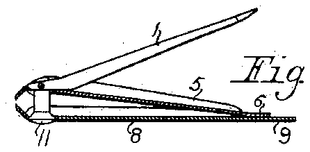
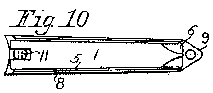
It is an object of this invention to produce a clip of special construction, having parts each of particular formation, and the whole of unique arrangement. It is believed the structure herein described is very simple in character, and cheap to manufacture and assemble, and it is a further object of this invention that when the parts are combined as set forth and are arranged in what is herein termed the closed position of the lever member there is no projecting point or edges or the like to catch in the pocket of the bearer. In the accompanying drawings the preferred construction of this invention is illustrated, and Fig. 1 represents a side view, slightly enlarged of the lever 0r file member. Fig. 2 is a view of the under side of the lever member showing the surface cross ridged as a nail file in the usual manner. Fig. 3 is a cross section of the lever member. Fig. 4 is a 2 side view of the upper and movable channel member. Fig. 5'is a cross section of the channel member shown in Fig. 4. Fig. 6 is a side view of the lower channel member, and Fig. 7 is a cross section view thereof. Fig. 8 is a partly sectional view lengthwise of this invention showing the lever member in its operating position, and all parts assembled. Fig. 9 is a side viewshowing all parts assembled with the lever member in its closed position and showing also that one channel member occupies the other and the lever member occupies one of the channel members. The Fig. 10 is a top view of all parts assembled.
Throughout the drawings and description the same number is used to refer to the same.
art. p Consider the drawings, a lever member 1 of angular form has a pointed end 2 for use incleaning the nails, and a file face 8 of any chosen design. The end of the lever member that is widest to recessed as illustrated and provided with a pivot pin 4.
The upper and narrower channel member 5 has a flat end 6 and a clipping edge 7 .The
1931. Serial';No. 532,621.
cross section of thismemberis set out in Fig. 5. The channel opens upwardly.
The lower and wider channel member 8 has a flat end 9 of about double the length of the like end of the member 5, and the lower channel member has also a clipping edge or end 10. The flat ends 6 of members 5 and 9 of member 8 are welded one upon the other in such manner that they are resiliently joined, and the upper channel member is normally sprung away from the lower channel member at their clipping ends as shown.
The parts are held together by means of a rotary stud 11, which is provided near the top with an upwardly inclined recess con-.
structed to receive the pivot pin 4 of the lever member.
In the operation of this invention, if the lever member is in its operating position as illustrated in Fig. 8 it will when operated press the channel member 5 downwardly and close the clipping edges together with considerable force. In this position of the parts the file surface 8 of the lever member is exposed for use. If while the lever member is raised as set out in Fig. 8 it be swung around in a horizontal circle, the stud 11 will turn with it and the lever will extend to the left hand side. In other words, the lever member 1 will now project oppositely from the position set forth in Fig. 8. Now, if the lever be turned over in a vertical plane it will be inverted and its position when closed will be that illustrated in Fig. 9. It will be understood that the lever member when in its closed position occupies the channel member 5, and the member 5 occupies the channel member 8. Thus no rough surfaces or points or corners are located outwardly and the whole is free from projections.
This invention is in no sense limited to the precise size, form or disposition of the parts disclosed as changes are believed'to be readily devised after knowledge of this invention.
Having now described this invention and its operation, I claim A finger nail clip, comprising two co-acting channel members, the channels of the said members opening in the same direction, one. of the said members being constructed to occupy the channel of the other member, each of said channel members having a clipping edge at one end, the said members being resiliently joined together, a lever member constructed to occupy an operating position and an inverted closed position, and means for pivotally connecting the said lever member with one of the channelmembers whereby the lever when operating presses upon the other channel member closing the said clipping edges, and the said lever mem-- her when in its closed position occupying the channel of the said member which occupies the channel of the other member.
In testimony whereof I aflix my signature.
MAXIMILIAN SCHNEFEL.

