- 1diameters r
- 2r
- 10blade body
- 11top blade
- 21bottom blade
- 31supporting shaft hole
- 51convex incline
- 52concave incline
- 53concave arc type edge
- 54convex arc type edge
- 55downward incline
- 100nail clipper
- 110supporting shaft
- 120lever
- 200nail clipper
- 210nail clipper body
- 211supporting shaft hole
- 220supporting shaft
- 230lever
Abstract
The present invention relates to a method of manufacturing arc type blades for a nail clipper, which corresponds to a curved surface of a finger nail, arc type blades and a nail clipper manufactured by the same. The method of manufacturing arc type blades for an nail clipper, comprises: forming a top blade and a bottom blade forming a blade body, so as to incline at a same inclination angle, so that one end of the top blade is connected to one end of the bottom blade; forming an inner surface of a downward incline of the top blade so as to be inward curved in an arc shape which has a predetermined curvature and is extended along the downward incline, and forming an end of the top blade so as to be a vertical plane for forming an edge; forming an inner surface of an upward incline of the bottom blade so as to be outward curved in an arc shape which has the same curvature as that of the arc shape in the top blade and which is extended along the upward incline, and an end of the bottom blade so as to be a vertical plane for forming an edge; allowing the two ends of the top and bottom blades to be in contact with each other and grinding the two ends simultaneously in the vertical plane, to form the edge which is inward curved in the arc shape at the end of the top blade and the edge which is outward curved in the arc shape at the end of the bottom blade, thereby forming the arc type nail clipper in which the curves of the concave and convex arc type edges are accurately in contact with each other.
Description
TECHNICAL FIELD
[0001] The present invention relates to a method of manufacturing arc type blades for a nail clipper and arc type blades and a nail clipper, and in particular, a method of manufacturing arc type blades for a nail clipper, which correspond to a curved surface of a finger nail, and arc type blades and a nail clipper manufactured by the same.
BACKGROUND ART
[0002] An arc type nail clipper has the characteristic in that blades are arc in shape from a front view, so as to correspond to a curved surface of a finger nail. Accordingly, upon cutting a finger nail by using the arc type nail clipper, no uncomfortable feeling is caused by the pressure first applied to both side ends of the finger nail or the finger nail is prevented from being broken. Since the arc type blades are considered as being very important when actually using the arc type nail clipper, a number of patent applications thereof have been filed thirty years ago. Nevertheless, the arc type blades are of an ideal idea only because these have not been realized as a product. That is, due to a problem in manufacturing, the arc type blades have not been commercialized or practically used.
[0003] Prior art of an arc type nail clipper relating to the present invention has been disclosed in a number of patents, Japanese Utility Model Publication Nos. Sho 49-8181 (Jan. 24, 1974), Sho 49-120419 (Oct. 16, 1974), Sho 52-66577 (May 17, 1977), Sho 51-119970 (Sep. 12, 1977), Sho 54-98369 (Jul. 11, 1979) and Sho 54-116468 (Aug. 15, 1979), Japanese Patent Publication No. 2005-74135 (Mar. 24, 2005), Japanese Utility Model Publication Hei 01-145305, U.S. Design Pat. No. 371,636, and the like.
[0004] In addition to the exemplification in the aforementioned prior art, many same ideas have been presented. Most prior art is desirous that the edges of top and bottom blades are in contact with each other in a curved surface. As a result of searching the prior art, no prior art describes a manufacturing technique for realizing the arc type blades as desired. That is, the prior art never describes the technology on how to form the edges of the top and bottom blades of a nail clipper in an arc shape in a three-dimensional space and how to make the edges to be accurately in contact with each other.
[0005] In U.S. Design Pat. No. 371,636, the edges of the top and bottom blades of a nail clipper are in contact with each other, forming an inclined arc shape in a three-dimensional space and corresponding to the curved surface of a finger nail. Likewise, although these arc type edges of the blades are possible in design, this prior art does not present how to overcome a technical problem in manufacturing technology.
[0006] Since most prior art does not present the technology for manufacturing the arc type blades, the arc type blades have not been commercially produced. Japanese Patent Publication No. 2005-74135, in which the difficult problem in manufacturing is a little more understood, attempts to realize the top and bottom blades in an arc shape in an entirely different structure, with the same object of use. However, since the top and bottom edges are independently and separately grinded, manufacturing expenses are increased. Moreover, since the bottom edge is not positioned to be close under a finger nail as much as a thickness of the bottom edge, it is not easy to cut the finger nail.
[0007] In a general nail clipper, top and bottom edges are extended from the top and bottom blade bodies, so as to be in contact with each other. Each of the top and bottom edges is formed to be inclined in shape and has a little curved surface in external appearance.
[0008] The top and bottom edges are simultaneously grinded to be sharpened, by using a grinding roller of a diameter corresponding to the curved surface. Then, when the diameter of the curved surface at the end of the edge is same as the diameter of the grinding roller, the top and bottom edges are generally to be horizontally parallel to each other, in a front view.
[0009] To form an edge in an arc shape in a front view of the edge, a middle part of the concave arc type edge needs to be formed to be inward curved in an arc shape, and a middle part of the bottom edge needs to be formed to be outward curved in an arc shape, so that the line of the top and bottom blades being in contact with each other is accurately in contact, to clearly cut a finger nail. However, it is very difficult to contact the curved surfaces of the top and bottom edges together, according to the shape of the edge which is inclined and extended from the top blade, the shape of the edge which is inclined and extended from the bottom blade, the diameter of the grinding roller, the accuracy of a processing machine, and the extent of depth to be grinded. Consequently, a gap may occur between the top and bottom edges in unpredictable directions, and an unusable product may be made, depending on the aforementioned different variables.
[0010] Most prior art discloses the description of the schematic shape of a nail clipper with arc type edges and the utility thereof, to be patented. However, the disclosure of most prior art is just an idea. Because no specific method of realizing the idea is presented, the prior art has not been practically used.
DISCLOSURE OF INVENTION
Technical Problem
[0011] The most important basic requirement for manufacturing arc type top and bottom edges of a nail clipper is to form the top and bottom edges which are accurately in contact with each other, by sufficiently allowing variation of a grinding depth of the top and bottom edges and simultaneously grinding the top and bottom edges.
[0012] The edges of the nail clipper are manually, semi-automatically or full-automatically grinded, using a grinding roller of a diameter corresponding to a diameter of a curved surface of an edge end. Manual grinding makes a big difference in a grinding result, depending on the extent of skill of an operator. Semi-automatic and automatic grinding generates deviation, depending on the dimension variation of a fixing unit for fixing the nail clipper, the variation of a transfer unit for automation and the extent of abrasion of a grinding belt.
[0013] Specifically, when the edges of the nail clipper are three-dimensionally formed in an arc point, although the top and bottom edges are in contact in any three-dimensional space, it is almost impossible to manufacture a nail clipper in which the curved surfaces of the top and bottom edges are in contact with each other while satisfying the aforementioned basic requirement. It may be possible to produce this kind of the nail clipper, in a small quantity, as handmade works or to be fit for the purpose. However, since the uniform manufacture of this kind of the nail clipper in a great quantity is not theoretically and technologically founded, there has been no product to be commercialized and practically use.
[0014] Therefore, it is an object of the present invention to provide a method of manufacturing arc type blades of a nail clipper, which are accurately in contact with each other when top and bottom edges are in contact with each other, on the conditions of two-dimensionally forming arc type edges to be in contact with each other, allowing the variation of a grinding depth as the aforementioned basic condition (the variation to be within a range of about +0.2 mm of a reference value), and grinding the top and bottom edges simultaneously, and arc type blades and a nail clipper manufactured by the same.
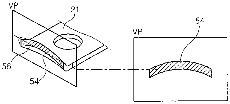
Technical Solution
[0015] In an arc type nail clipper which comprises a blade body, and a lever formed by a supporting shaft through a supporting shaft hole formed in the blade body, the arc type nail clipper in which the curves of concave and convex arc type edges are accurately in contact with each other is manufactured by a method of manufacturing arc type blades for the nail clipper, which comprises: forming a top blade and a bottom blade forming a blade body, so as to incline at a same inclination angle, so that one end of the top blade is connected to one end of the bottom blade; forming an inner surface of a downward incline of the top blade so as to be inward curved in an arc shape which has a predetermined curvature and is extended along the downward incline, and forming an end of the top blade so as to be a vertical plane for forming an edge; forming an inner surface of an upward incline of the bottom blade so as to be outward curved in an arc shape which has the same curvature as that of the arc shape in the top blade and which is extended along the upward incline, and an end of the bottom blade so as to be a vertical plane for forming an edge; allowing the two ends of the top and bottom blades to be in contact with each other and grinding the two ends simultaneously in the vertical plane, to form the edge which is inward curved in the arc shape at the end of the top blade and the edge which is outward curved in the arc shape at the end of the bottom blade.
[0016] In an arc type nail clipper which comprises a nail clipper body with a supporting shaft hole formed at one side thereof, a blade body with a supporting shaft hole and comprising a top blade and a bottom blade, and a lever positioned on the nail clipper body and connected to the blade body and the nail clipper body by a supporting shaft, for performing a lever function, the arc type nail clipper in which the curves of concave and convex arc type edges are accurately in contact with each other is manufactured by a method of manufacturing arc type blades for the nail clipper, which comprises: forming a top blade and a bottom blade forming a blade body, so as to incline at a same inclination angle, so that one end of the top blade is connected to one end of the bottom blade; forming an inner surface of a downward incline of the top blade so as to be inward curved in an arc shape which has a predetermined curvature and is extended along the incline, and forming an end of the top blade so as to be a vertical plane for forming an edge; forming an inner surface of an upward incline of the bottom blade so as to be outward curved in an arc shape which has the same curvature as that of the arc shape in the top blade and which is extended along the incline, and an end of the bottom blade so as to be a vertical plane for forming an edge; allowing the two ends of the top and bottom blades to be in contact with each other and grinding the two ends simultaneously in the vertical plane, to form the edge which is inward curved in the arc shape at the end of the top blade and the edge which is outward curved in the arc shape at the end of the bottom blade.
ADVANTAGEOUS EFFECTS
[0017] In accordance with the method of manufacturing arc type blades for a nail clipper and arc type blades and a arc type nail clipper of the present invention, the edge of a top blade and edge of a bottom blade are simultaneously grinded in one vertical plane while these are in contact with each other, so that an concave arc type edge in an arc shape is formed at the end of the top blade and an convex arc type edge in an arc shape is formed on the end of the bottom blade, thereby manufacturing arc type edges of an arc type nail clipper in which the concave and convex arc type edges are accurately in contact with each other.
[0018] Specifically, since the curves of the concave and convex arc type edges in the arc shape do not change, irrespective of the variation of a grinding depth, consequently an elaborate product without any gap between the concave and convex arc type edges formed in the arc shape is manufactured, and a great quantity of the products are uniformly manufactured.
DESCRIPTION OF DRAWINGS
[0019] The accompanying drawings illustrate preferred embodiments of the present invention. This invention may, however, be embodied in different forms and should not be construed as limited to the embodiments set forth in the drawings.
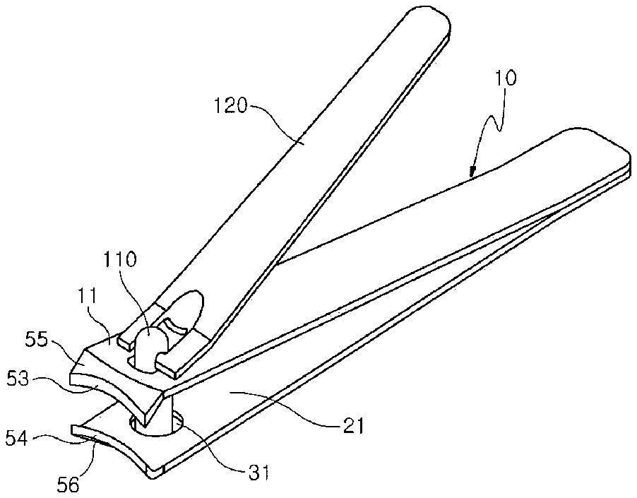
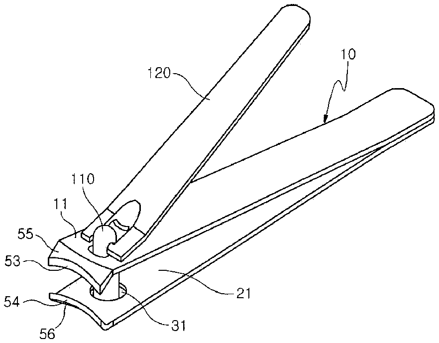
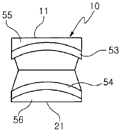
[0020] FIG. 1A is a perspective view of an arc type nail clipper according to an embodiment of the present invention, and FIG. 1B is a front view of a blade body for the nail clipper shown in FIG. 1A ;
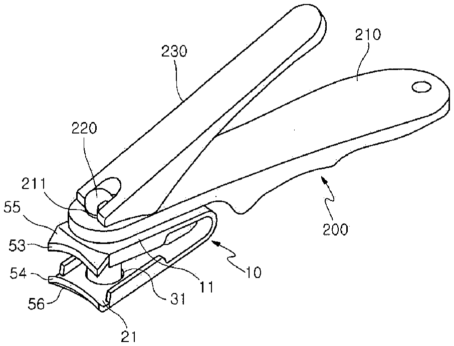
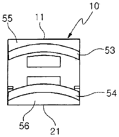
[0021] FIG. 2A is a perspective view of an arc type nail clipper according to another embodiment of the present invention, and FIG. 2B is a front view of a blade body for the nail clipper shown in FIG. 2A ;
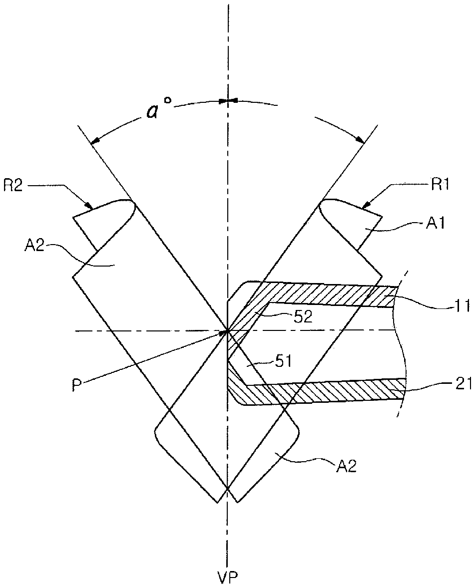
[0022] FIG. 3 is a view illustrating a principle of blades of the arc type nail clipper of the present invention;
[0023] FIG. 4 is a view for explaining the blades of the arc type nail clipper of the present invention;
[0024] FIG. 5A is a partially cut perspective view of an internal incline of a top blade of the present invention, and FIG. 5B is a partially cut perspective view of an internal incline of a bottom blade thereof;
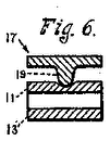
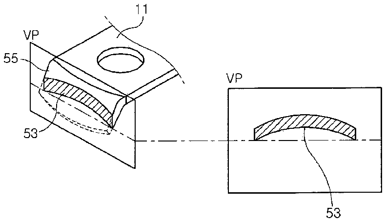
[0025] FIG. 6A illustrates that an end of the top blade is cut based on a vertical plane and is a front view of a cut section being in contact with the vertical plane, and FIG. 6B illustrates that an end of the bottom blade is cut based on a vertical plane and is a front view of a cut section being in contact with the vertical plane;
[0026] FIG. 7A is a partially cut inside perspective view of an edge formed by cutting the end of the internal incline of the top blade; and FIG. 7B is a partially cut inside perspective view of an edge formed by cutting the end of the internal incline of the bottom blade; and
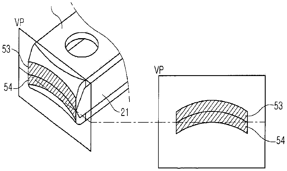
[0027] FIG. 8 illustrates concave and convex arc type edges formed in an arc shape, which are in contact with each other, by contacting the edge of the top blade and the edge of the bottom blade together and simultaneously grinding the edges in the vertical plane.
BEST MODE
[0028] The present invention will now be described more fully hereinafter with reference to the accompanying drawings, in which preferred embodiments of the invention are shown.
[0029] FIG. 1A is a perspective view of an arc type nail clipper 100 according to an embodiment of the present invention, and FIG. 1B is a front view of a blade body for the nail clipper 100 shown in FIG. 1A . FIG. 2A is a perspective view of an arc type nail clipper 200 according to another embodiment of the present invention, and FIG. 2B is a front view of a blade body for the nail clipper 200 shown in FIG. 2A .
[0030] In FIG. 1A , the nail clipper 100 comprises a blade body 10 and a lever 120 . The blade body 10 and the lever 120 are connected by a supporting shaft 110 through a supporting shaft hole 31 formed in the blade body 10 .
[0031] In FIG. 2A , the nail clipper 200 comprises a nail clipper body 210 , a blade body 10 , and a lever 230 . The nail clipper body 210 includes a supporting shaft hole 211 at one end thereof. The blade body 10 comprises a supporting shaft hole 31 , a top blade 11 and a bottom blade 21 . The lever 230 is positioned on the nail clipper body 210 and is connected to the blade body 10 and the nail clipper body 210 by a supporting shaft 220 , for performing a leverage. The blade body 10 is rotated at 360 degrees around the supporting shaft 220 with respect to the nail clipper body 210 .
[0032] In FIG. 1A , the blade body 10 comprises a top blade 11 and a bottom blade 21 . One end of the top blade 11 and one end of bottom blade 21 are fixed together by spot welding. In FIG. 2A , the blade body 10 is formed by bending one side of the top blade 11 and the bottom blade 21 so as to be in one body.
[0033] In FIG. 1A , the blade body 10 are made in one body by the spot welding of the top and bottom blades 11 and 21 which are respectively manufactured by a press process. In FIG. 2A , the blade body 10 are formed in one body by bending the top and bottom blades 11 and 21 in the press process. The technology forming arc type edges according to the present invention can be equally realized in both nail clippers which are different in shape as shown in the aforementioned embodiments. Thus, the blade body of the nail clipper to be described with reference to the drawings will be indicated by the same reference numeral, “ 10 ”.
[0034] The blade body 10 comprises the top blade 11 and the bottom blade 21 . The top blade 11 and the bottom blade 21 are formed to be same slant so that one end of each blade is connected to each other.
[0035] The top blade 11 includes a downward incline 55 and an end. An inner surface of the downward incline 55 is formed in a concave arc shape which has a predetermined curvature and which is extended along the downward incline 55 . The end of the top blade 11 is formed to be a vertical plane, for forming a concave arc type edge 53 . The bottom blade 21 includes an upward incline 56 and an end. An inner surface of the upward incline 56 is formed in a convex arc shape which has the same curvature and which is extended along an upward incline 56 . The end of the bottom blade 21 is formed to be a vertical plane, for forming a convex arc type edge 54 . While the concave arc type edge 53 and the convex arc type edge 54 are in contact to each other, the concave arc type edge 53 and the convex arc type edge 54 are grinded simultaneously in a vertical plane, thereby forming the concave arc type edge 53 in an concave arc shape in the top blade 11 and forming the convex arc type edge 54 in an convex arc shape in the bottom blade 21 , to form the arc type nail clipper 100 or 200 in which the curves of the concave and convex arc type edges are accurately in contact with each other.
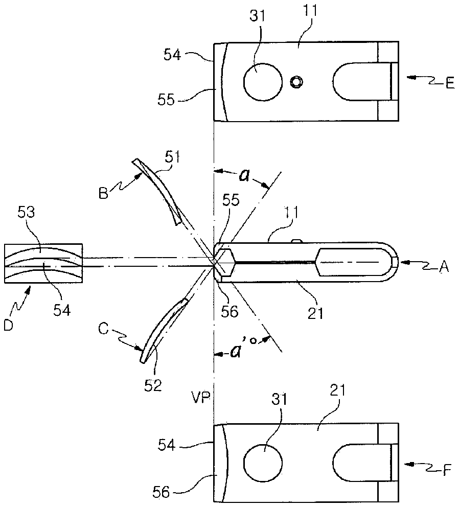
[0036] FIG. 3 shows a principle of blades of the arc type nail clipper of the present invention. For example, a cylinder is lengthwise divided into two parts. A half cylinder is indicated as A 1 and the other half cylinder is indicated as A 2 . A diameter R 1 of a half cylinder A 1 is identical with a diameter R 2 of the other half cylinder A 2 . When the half cylinders A 1 and A 2 are stood symmetrically, one is allowed to rotate at a predetermined angle a° to the left based on a center intersection point P of the edges, relative to FIG. 3 , and the other is allowed to symmetrically rotate to the right at an angle a′°. Then, the ends of the blades are cut, together the half cylinders A 1 and A 2 , along a vertical plane VP based on the center intersection point P and the cut parts to the left, relative to FIG. 3 , are removed. As a result, the inner surface of the concave incline 52 of the top blade 11 is formed in a concave arc shape, along an inward curved surface of an arc of the half cylinder A 1 , and the inner surface of the incline 51 of the bottom blade 21 is formed in a convex arc shape, along an outward curved surface of an arc of the half cylinder A 2 , so that the concave incline 52 of the top blade 11 formed in the concave arc shape is in contact with the incline 51 of the bottom blade 21 formed in the convex arc shape.
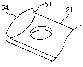
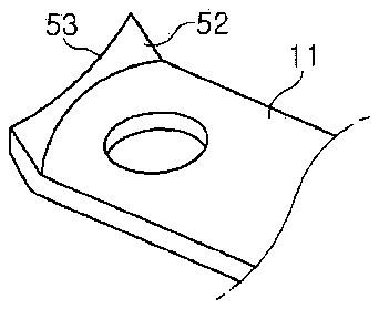
[0037] FIG. 4 is a view for explaining the blades of the arc type nail clipper of the present invention. Part A is a side view of the blade body, part B illustrates the convex incline 51 which is the inner surface of the bottom blade 21 , part C illustrates the concave 52 incline which is the inner surface of the top blade 11 , part D is a front view of the blade body shown in part A, and parts E and F are respectively a plan view and a bottom view of the blade body shown in part A.
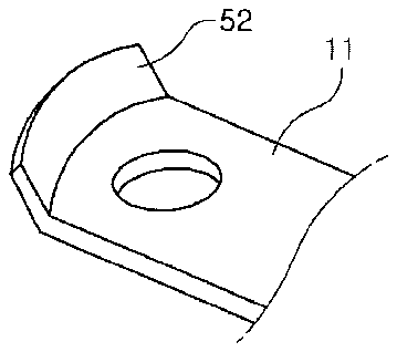
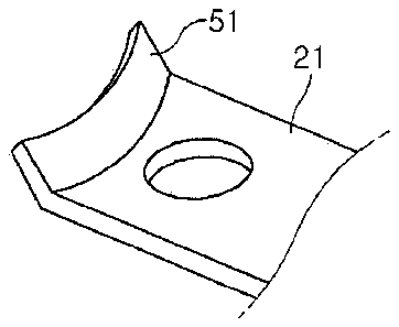
[0038] As illustrated in FIGS. 4 through 5B , a front end of the top blade 11 externally forms a convex surface 55 , along a slant while internally forming the concave incline 52 , and a front end of the bottom blade 21 externally forms a concave surface 56 , along a slant while internally forming the convex incline 51 . Thereby, the convex incline 51 forming a convex arc type edge and the concave incline 52 forming a concave arc type edge respectively have the diameters R 1 and R 2 of the curved surfaces of the half cylinders. Here, the diameters R 1 and R 2 of the curved surfaces of the half cylinders need to be identical with each other, to form a top concave arc type edge 53 and a convex arc type edge 54 so as to be fitted into each other, as shown in part D of FIG. 4 .
[0039] In FIG. 5A , the concave incline 52 of the top blade 11 has the same concept as the inner surface of the half cylinder A, and in FIG. 5B , the convex incline 51 of the bottom blade 21 has the same concept as the inner surface of the half cylinder A 2 , wherein the half cylinders A 1 and A 2 need have the same diameter.
[0040] FIG. 6A illustrates that the end of the top blade 11 is cut based on the vertical plane VP and is a front view of a cut section being in contact with the vertical plane VP, and FIG. 6B illustrates that the end of the bottom blade is cut based on the vertical plane VP and is a front view of a cut section being in contact with the vertical plane VP. FIG. 7A is an inside view of the edge of the top blade 11 which is completely cut, and FIG. 7B is an inside view of the edge of the bottom blade 21 which is completely cut.
[0041] In FIG. 8 , while the concave arc type edge 53 of the top blade 11 and the convex arc type edge 54 of the bottom blade are fitted into each other, the concave and convex arc type edges 53 and 54 are simultaneously grinded by moving the vertical plane VP to be closer toward the top and bottom blades 11 and 21 within a range of grinding variation, to form the concave and convex arc type edges 53 and 54 which are fitted into each other. Further, FIG. 8 is a front view of the edges being in contact with the vertical plane VP.
[0042] As described above, the convex surface 55 is formed on the external of the front end of the top blade 11 , along the slant, and the concave surface 56 is formed on the external of the front end of the bottom blade 21 , along the slant. Here, the nail clipper is effectively and comfortably positioned under a nail by the external concave surface 56 of the bottom blade 21 .
[0043] In accordance with the present invention, the internal inclines where the edges are finally formed have the same inclination angle in the top blade 11 and the bottom blade 21 and form the concave incline 52 and the convex incline 51 having the same diameter, thereby realizing the arc type nail clipper in which the concave arc type edge 53 is accurately in contact with the convex arc type edge 54 in the two-dimensionally vertical plane.
[0044] The invention has been described using preferred exemplary embodiments. However, it is to be understood that the scope of the invention is not limited to the disclosed embodiments. On the contrary, the scope of the invention is intended to include various modifications and alternative arrangements within the capabilities of persons skilled in the art using presently known or future technologies and equivalents. The scope of the claims, therefore, should be accorded the broadest interpretation so as to encompass all such modifications and similar arrangements.
