

- 2line
- 3line
- 6closed or
- 12stud
- 13cutter
- 16head
- 17lever
- 18slot
- 20pivot
- 21slide
- 27slot
- 28n finger-piece
- 29slot
- 30slot
- 33it stud
- 81ringer-piece
Description
PATENTED FEB. 5, 1907.
M. WOOSTER. NAIL CLIPPER.
APPLICATION FILED 0(]'l.5 1906.
s E s S M W W iinrrnn Specification of Letters Patent.
assess.
Patented Feb. 5, 1907.
Application filed October 5,1906- Scrisl No- 337,558.
To all whom if 7)L(l 7/ courier-11,:
.Be it known that l, ALBERT M. Woosrnn, a citizen of the United States, residing at Bridgeport, county of Foiriield, State of Connecticut, have invented s new and useful Nail-Clipper, of which the following is a specification.
This invention relates to the class of nailclippers in which two members are connected together at one end, are provided with cuttors at the other end, which are normally held apart either by a spring or by the resiliency of one or both of the members themselves and in which the cutters are moved to the closed or operative position by means of a lever pivoted to one of the members and bearing upon the other member; and the invention has for its object to provide a. nailclippcr oi this character in which a lover of the second order pivoted to one member and not connected to the other member shall have its fulcrum on a cross-pin in the other member.
The invention further consists in certain details of construction which will be hereinalter fully described and then specifically pomted out in the claims hereunto appem'lcd.
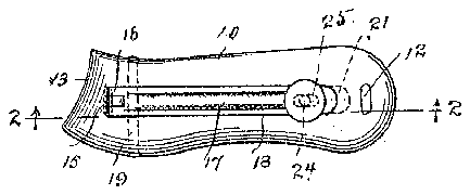
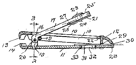
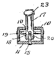
In the accompanying drawings, forming a port of this specification, Figure 1 is a plan view of my novel clipper in the closed position; Fig. 2 a longitudinal section on the line 2 2 in Fig. 1 looking in the direction of the arrow, the cutters being in the open position; and Fig. 3 is a transverse section on the line 3 3 in Fig. looking in the direction of the arrow.
10 denotes in member which for convenience I will term the upper member, and 11 a member which for convenience l. will term the lower member. Both members are struck out and formed from shoot me ml and are connected together at one end by a stud or rivet, (indicated by 12.)
per member is provided at its opposite end The upwith a cutter 13 and the lower member with l o coacting cutter 14-. in the form of clipper illustrated in the drawings the members are nornuilly separated by the resiliency of the lower member. The lower member 1s pro vidcd with an upwordlymxtcnding stud l5, lying wholly between the members, to which the head 16 of the lever 17 is pivoted, as at 20. This lever extends through a slot 18 in the upper member and has its fulcrum on a cross-pin 19 in the upper member. The head of the lever is so formed and pivot 20's0 l l l l l l ,full width of the under surface located that when the jaws are in the open position, as in Fig. 2, pivot 20 will lie in a plane below the plane of cross-pin 19, which is the fulcrum, so that when the operator presses down upon the free end of the lever the cutters will be moved to the closed or 6})- erative position. In the closed position, as in Fig. 1, the lever posses down into slot 18 in the upper member. This structure enables the wceringsurfeccs to be provided practically proportioned to the amount of movement or rubbing contact to which they are subjected in use. In use greater friction occurs between the pin 19 and the under surface of the lever than at the ivot 20, and this greater friction is borne y the entire 7 of the lever and the surface of the, pin 19, which, being straight, can easily and economically be nnidc of the 1) Pet of metal to stand the wean, such as hardened steel, if desired. On the other hand, as the movement is relotively slight at the pivot 20 the foot that a lesser amount of metal of the lever is cngcqed with said pivot does not shorten the life oi the implemcnt.
The lever is locked in the closed position by means of a slide 21 on the under side of the lever, the forward end of which is adopted topass under the metal of the upper member at the end of the slotto lock the lever in the closed position, the point of locking engagement with the slide being indicated by 22 in Fig. 2. The slide is operated by means of n finger-piece 28, lying upon the top of the lever, which is connected with the slide by means of c stud. 24, which passes through a slot in the levo shown by dottc lines only. The slide is retained against Stll except longitudinal movement by'niczms of a tailpiece-1Z6, the tip of which engages a slot 27, indicated by dotted lines only.
28 denotes a nail-cleaner which is adopted to be retracted be tween the members or to be projected for use, as indicated by dotted lines in Fig. 2. This nail-clcener lies on the upper side of the lower member and posses through a. slot 29 in stud 12 and a. slot 30 in the end of the upper member. t is operated by means of o. ringer-piece 81, vhich is connected to the nail-cleaner by means of it stud 33, which passes through a. slot- 32 in the lower member.
Having thus described my invention, I claim--- 1. A nail-clipper comprising two members IIO having cutters,-1neans for normally sepae rating the cutters, a lever having its inner end pivoted to the lower member, and a cross-pin supported by the other member and extending under the lever, the said lever bearing loosely on the cross-pin.
2. A nail-clipper comprising two men'i'bers having cutters, means for normally sepa rating the cutters, an angular lever having its inner end pivoted to the lower member, and a cross-pin supported by the other nezm her and extending under the angle of the lever, the said lever hearing loosely on the to the stud, said lever passing" through the slot and bearing loosely on the cross-pin.
4. A nail-clipper comprising members provided with cutters, one of said members having an inwardly-projecting stud and the other member a slot and cross-pin, a lever passing through the slot and having a head pivoted at its inner end on the stud and its bearing on the eross-pin, and a slide on said lever adapted to engage the metal at the end of the slot to lock the cutters at the closed position when the lever is pressed into the slot.
In testimony whereof I aflix my signature in presence of two witnesses.
ALBERT M. ,WOOSTER.
Vitnesses I J. H. CRossLEY, S. W. ATHERToN.


