

- 2section
- 10nail trimmer
- 12jaw pieces
- 16fastener
- 18headed pin
- 20lever
- 22cross pin
- 24top surface
- 26heel portion
- 32transparent window piece
- 36steel pieces
- 11235 usc
Abstract
A nail trimmer and method in which a transparent viewing area is provided immediately to the rear of one of a pair of cutting edges to enable observation of the inserted nail part while trimming the nail.
Description
CROSS-REFERENCE TO RELATED APPLICATION
[0001] This application claims the benefit of U.S. provisional serial No. 60/278,844, filed Mar. 26, 2001.
BACKGROUND OF THE INVENTION
[0002] This invention concerns nail clippers of the well known type having a pair of jaws operated by an angled lever pivoted to an upper jaw just to the rear of its cutting edge. This design has achieved great commercial success, but has one disadvantage in that when a part of the nail to be trimmed is inserted between the jaws, that part of the nail cannot be seen by the user, hampering the ability of the user to trim the nail exactly as desired.
[0003] It is the object of the present invention to provide a nail trimmer of this type which allows observation of the part of the nail to be trimmed.
SUMMARY OF THE INVENTION
[0004] The above object as well as others which will become apparent upon a reading of the following specification and claims are achieved by providing a transparent area in the upper jaw just to the rear of the upper jaw cutting edge, allowing a user to readily observe the nail part inserted between the trimmer cutting edges. In a first embodiment of the nail trimmer, a window opening is formed just to the rear of the cutting edge, which can have a transparent window piece installed therein.
[0005] In a second embodiment, the upper jaw is formed of a strong transparent plastic material, and a steel cutting edge is bonded to the leading end of the jaw to perform the cutting action. The inserted nail part is viewable through the transparent jaw.
DESCRIPTION OF THE DRAWINGS
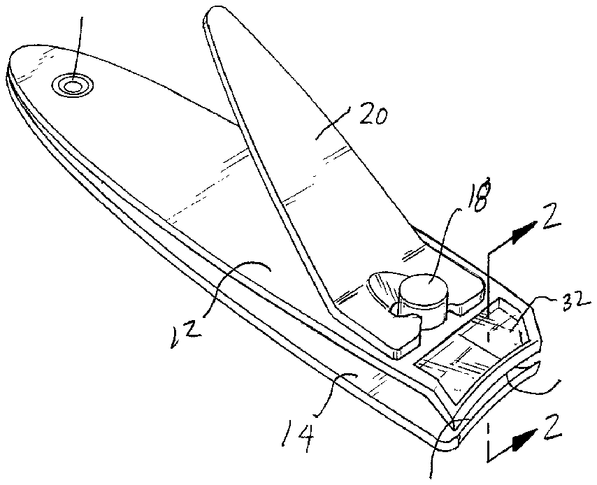
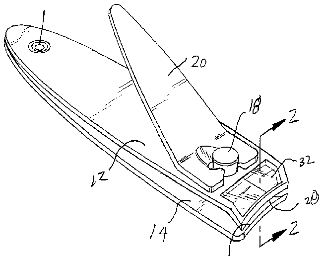
[0006] [0006]FIG. 1 is a perspective view of a first embodiment of a nail trimmer according to the present invention.
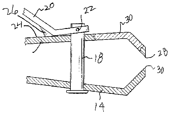
[0007] [0007]FIG. 2 is an enlarged view of the section 2 - 2 taken in FIG. 1.
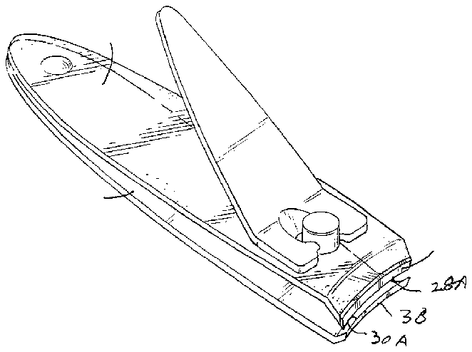
[0008] [0008]FIG. 3 is a perspective view of a second embodiment of a nail trimmer according to the present invention.
DETAILED DESCRIPTION
[0009] In the following detailed description, certain specific terminology will be employed for the sake of clarity and a particular embodiment described in accordance with the requirements of 35 USC 112, but it is to be understood that the same is not intended to be limiting and should not be so construed inasmuch as the invention is capable of taking many forms and variations within the scope of the appended claims.
[0010] [0010]FIG. 1 shows a first embodiment of a nail trimmer 10 according to the invention, which is shown as an improvement of a general type of nail trimmer in wide use. This includes an upper and lower chrome plated steel jaw pieces 12 , 14 which are elongated and connected together at rear end by a fastener 16 .
[0011] The jaw pieces 12 and 14 are formed so as to normally assume a separated position with respect to each other, urged outwardly by the resilience of the pieces against a stop provided by a headed pin 18 installed at the forward end of the jaw pieces 12 , 14 .
[0012] An angled operating lever 20 is held on the upper end of the pin by a cross pin 22 . In the operating position shown, a heel portion 26 of the lever 20 engages the top surface 24 of the upper jaw 12 , and upon depressing the free end of the lever 20 , the upper and lower jaw pieces 12 , 14 are brought together in the well known manner.
[0013] Each jaw piece 12 , 14 has a down turned slightly curved cutting edge 28 , 30 positioned in opposition to each other, which are forced together by the movement of the jaw pieces 12 , 14 towards each other, to create the cutting action on the tip of a nail inserted between the same.
[0014] According to the present invention, an area of the upper jaw piece 12 immediately to the rear of the upper cutting edge 28 is made to be transparent so as to allow observation of the nail part inserted between the cutting edges 28 , 30 . In the embodiment shown in FIGS. 1 and 2, this is provided by a transparent window piece 32 installed in a window opening 34 formed into the upper jaw piece 12 just to the rear of the upper cutting edge 28 . The window piece can be constructed of glass or plastic and glued in place.
[0015] [0015]FIG. 3 shows a second embodiment of a nail clipper 34 according to the invention, where the jaw pieces 12 A, 14 A are formed of a strong transparent plastic such as polycarbonate with cutting edges 28 A, 30 A provided on steel pieces 36 , 38 bonded to the plastic.
[0016] Thus, the user can readily observe the nail area inserted between the cutting edges 28 , 30 for easier more effective nail trimming.
