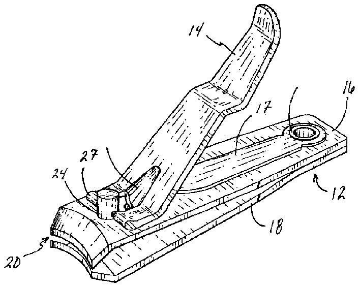
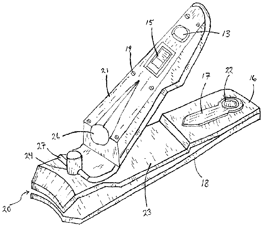
- 10nail clipper
- 12clipper portion
- 13cover
- 14thumb lever
- 15switch
- 16top blade
- 18blade
- 19bolts or screws
- 20cutting area
- 21lighting system housing
- 22rivet
- 23housing
- 24post
- 25tab
- 26lighting system
- 27post attachment section
- 29tang
- 31light opening
- 34power source
- 36nail illumination region
Abstract
An illuminated nail clipper. The illustrated embodiment of the illuminated nail clipper includes a thumb lever including a tab and post attachment section. Additionally, the embodiment would have a bottom clipper portion, including a top blade and a bottom blade. There is also a rivet positioned through a first end of each of the top and bottom blades. A post may be positioned through a second end of each of the top and bottom blades. A cutting region would be formed between the top and bottom blades at the second end of each. Additionally, there is a lighting system that includes a power source and a light source. The light source would be electrically coupled to the power source. The light source would be positioned sufficiently high over a top surface of the thumb lever to project a beam of light over and around a top of the post to create a nail illumination region, which would be located just beyond the cutting area.
Description
BACKGROUND OF THE INVENTION
[0001] 1. Field of the Invention
[0002] The present invention relates to nail clippers, specifically it relates to nail clippers with a lighting system attached thereto.
[0003] 2. Description of the Related Art
[0004] In the related art, it has long been known to use nail clippers for trimming finger and toe nails. The following are examples of related art are provided herein for their related teachings, and are herein incorporated by reference for their supportive teachings:
[0005] U.S. Patent Publication No.: US2002/0134395, by Hermiz, is a nail clipper with viewing window. There is taught a nail trimmer and a method in which a transparent viewing area is provided immediately to the rear of one of a pair of cutting edges to enable observation of the inserted nail part while trimming the nail.
[0006] U.S. Pat. No. 3,680,210 is a clipper device such as toenail clippers with a hollow domed shaped element serving as a magnifying lens and rigidly secured to the outer edges of one of the clipper blades. The lens is wide enough to cover bother blades when their cutting edges are in abutting position, thus allowing the user to obtain a close magnified view of what he is cutting, with the dome shaped element acting as a barrier to prevent pieces of clipped nail from being propelled into the face of the user.
[0007] U.S. Pat. No. 5,678,919, by Huang, is an illuminating scissors including a pair of blades pivotally joined in an intermediate portion thereof by a bolt engaged with a hexagonal lock nut and each having a handle at an end thereof, a cylindrical housing mounted on one of the blades, a light bulb arranged in a cylindrical edge of the cylindrical housing, a battery fitted in the cylindrical housing and electrically connected with the light bulb, and a switch mounted on the cylindrical housing and electrically connected with the battery and the light bulb.
[0008] U.S. Pat. No. 6,142,769, by Walker, is a multi-purpose tool including an elongated body portion. The plurality of tools is coupled with respect to the elongated body portion. The plurality of tools includes a serrated blade, a cork screw, a retractable pen, a refillable lighter, a bottle opener, and a flashlight.
[0009] U.S. design patent D448,523, by Kramer, is a standard nail clipper design having a particular ornamental shape.
[0010] What is needed is a nail clippers with an integral lighting system that solves one or more of the problems described herein and/or one or more problems that may come to the attention of one skilled in the art upon becoming familiar with this specification.
SUMMARY OF THE INVENTION
[0011] The present invention has been developed in response to the present state of the art, and in particular, in response to the problems and needs in the art that have not yet been fully solved by currently available nail clippers. Accordingly, the present invention has been developed to provide a nail clipper, specifically, a nail clipper with a lighting system attached, mounted, coupled or formed thereto.
[0012] It is a feature of one embodiment of the illustrated invention to provide an illuminated nail clipper. The embodiment of the illuminated nail clipper would comprise a thumb lever including a tab and post attachment section. Additionally, the embodiment would have a bottom clipper portion, including a top blade and a bottom blade. There is also a rivet positioned through a first end of each of the top and bottom blades. A post may be positioned through a second end of each of the top and bottom blades. A cutting region would be formed between the top and bottom blades at the second end of each. Additionally, there is a lighting system that includes a power source and a light source. The light source would be electrically coupled to the power source. The light source would be positioned sufficiently high over a top surface of the thumb lever to project a beam of light over and around a top of the post to create a nail illumination region, which would be located just beyond the cutting area.
[0013] Reference throughout this specification to features, advantages, or similar language does not imply that all of the features and advantages that may be realized with the present invention should be or are in any single embodiment of the invention. Rather, language referring to the features and advantages is understood to mean that a specific feature, advantage, or characteristic described in connection with an embodiment is included in at least one embodiment of the present invention. Thus, discussion of the features and advantages, and similar language, throughout this specification may, but do not necessarily, refer to the same embodiment.
[0014] Furthermore, the described features, advantages, and characteristics of the invention may be combined in any suitable manner in one or more embodiments. One skilled in the relevant art will recognize that the invention can be practiced without one or more of the specific features or advantages of a particular embodiment. In other instances, additional features and advantages may be recognized in certain embodiments that may not be present in all embodiments of the invention.
[0015] These features and advantages of the present invention will become more fully apparent from the following description and appended claims, or may be learned by the practice of the invention as set forth hereinafter.
BRIEF DESCRIPTION OF THE DRAWINGS
[0016] In order for the advantages of the invention to be readily understood, a more particular description of the invention briefly described above will be rendered by reference to specific embodiments that are illustrated in the appended drawings. Understanding that these drawings depict only typical embodiments of the invention and are not therefore to be considered to be limiting of its scope, the invention will be described and explained with additional specificity and detail through the use of the accompanying drawings, in which:
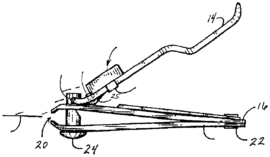
[0017] FIG. 1 illustrates a prior art nail clipper design;
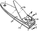
[0018] FIG. 2 illustrates a side view of one embodiment of the invention in the form of a lighted nail clippers;
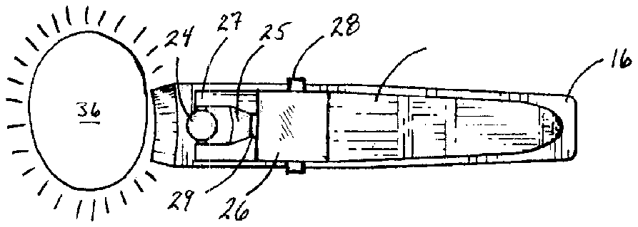
[0019] FIG. 3 illustrates a top view of the lighted nail clippers of FIG. 2 ;
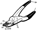
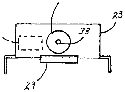
[0020] FIG. 4 illustrates a front view of the lighting device removed from the clippers; and
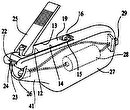
[0021] FIG. 5 illustrates a perspective view of another embodiment of the light nail clipper.
DETAILED DESCRIPTION OF THE INVENTION
[0022] For the purposes of promoting an understanding of the principles of the invention, reference will now be made to the exemplary embodiments illustrated in the drawings, and specific language will be used to describe the same. It will nevertheless be understood that no limitation of the scope of the invention is thereby intended. Any alterations and further modifications of the inventive features illustrated herein, and any additional applications of the principles of the invention as illustrated herein, which would occur to one skilled in the relevant art and having possession of this disclosure, are to be considered within the scope of the invention.
[0023] Reference throughout this specification to “one embodiment,” “an embodiment,” or similar language means that a particular feature, structure, or characteristic described in connection with the embodiment is included in at least one embodiment of the present invention. Thus, appearances of the phrases “one embodiment”, “an embodiment,” and similar language throughout this specification may, but do not necessarily, all refer to the same embodiment, different embodiments, or component parts of the same or different illustrated invention. Additionally, reference to the wording “an embodiment,” or the like, for two or more features, elements, etc. does not mean that the features are related, dissimilar, the same, etc. The use of the term “an embodiment,” or similar wording, is merely a convenient phrase to indicate optional features, which may or may not be part of the invention as claimed.
[0024] Each statement of an embodiment is to be considered independent of any other statement of an embodiment despite any use of similar or identical language characterizing each embodiment. Therefore, where one embodiment is identified as “another embodiment,” the identified embodiment is independent of any other embodiments characterized by the language “another embodiment.” The independent embodiments are considered to be able to be combined in whole or in part one with another as the claims and/or art may direct, either directly or indirectly, implicitly or explicitly.
[0025] Finally, the fact that the wording “an embodiment,” or the like, does not appear at the beginning of every sentence in the specification, such as is the practice of some practitioners, is merely a convenience for the reader's clarity. However, it is the intention of this application to incorporate by reference the phrasing “an embodiment,” and the like, at the beginning of every sentence herein where logically possible and appropriate.
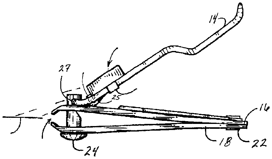
[0026] FIG. 1 illustrates a prior art nail clipper design. Specifically, there is a nail clipper 10 , having a bottom clipper portion 12 and a top thumb lever 14 . The bottom clipper portion includes a top blade 16 and a bottom blade 18 , which are held together with rivet 22 at a first end, and held together by a post 24 on the other end. The top and bottom blades 16 and 18 for a cutting region 20 . The thumb lever 14 includes a tab 25 and post attachment section 27 .
[0027] One skilled in the art will easily understand the typical operation of the mechanical features of the illustrated embodiments. Specifically, a user will typically force the thumb lever 14 downward toward the clipper portion 12 . The thumb lever 14 will pivot around post attachment section 27 , and tab 25 is forced against top blade 16 and moving it downward. The downward motion of blade 16 will eventually come into contact with blade 18 , thus causing cutting section 20 to cut a nail that is placed therein.
[0028] FIGS. 2 and 3 illustrate one embodiment of the invention in the form of a lighted nail clipper 10 . Specifically, in addition to what has already been discussed regarding FIG. 1 , there is a lighting system 26 mounted to the thumb lever 14 . In one embodiment, there is an attachment device, illustrated in the form of brackets 28 that couple to the thumb lever 14 and hold the lighting system to the lever 14 . There is also, in this embodiment, a tang 29 that is designed to specifically fit within the space created by the tab 25 because the tab is bent downward from the plane of the lever 14 . The purpose of the tang 29 is to prevent the lighting system 26 from slipping away from the cutting area 20 , because many thumb levers are often tapered and would cause the lighting system 26 to slip away from the clipping area 20 .
[0029] It is noted that the light source 30 is positioned sufficiently high over the top surface of the thumb lever 14 to project a beam of light 30 over and around the top of the post 24 . Thus, a nail illumination region 36 , located just beyond the cutting area 20 , will be created sufficiently close to the cutting region 20 to assist the user to clearly see the nail during a nail cutting operation.
[0030] FIG. 4 illustrates a front view of the lighting device removed from the clipper 10 . Specifically, in one embodiment, the lighting system includes a light opening 31 , which may be in the form of a hole in the housing 23 , or may be a cone formed from the housing material, for example. There is also a light source 33 , which may be in the form of a light bulb or light emitting diode (LED), for example. Additionally, there is a power source, illustrated as a battery 33 that is located within the lighting system housing. One skilled in the art will easily understand that there is electrical connection (not illustrated) formed between the power source 34 and the light 33 .
[0031] FIG. 5 illustrates a perspective view of another embodiment of the light nail clipper 10 . In addition to the invention shown in FIG. 1 , this variation of the nail clipper includes a lighting system 26 that is fixably mounted in a groove on the top side of the lighting system housing 21 that is fixably attached to the lever 14 via a plurality of bolts or screws 19 . Additionally, there is a switch 15 designed to allow users to activate or deactivate the lighting system 26 ; and a cover 13 concealing the power source in the form of a battery. Further, after using the nail clipper 10 , a user may invert the lever 14 enabling the top side of lighting system housing 21 to rest in the recessed surface 23 .
[0032] It is understood that the above-described embodiments are only illustrative of the application of the principles of the present invention. The present invention may be embodied in other specific forms without departing from its spirit or essential characteristics. The described embodiment is to be considered in all respects only as illustrative and not restrictive. The scope of the invention is, therefore, indicated by the appended claim rather than by the foregoing description. All changes which come within the meaning and range of equivalency of the claims are to be embraced within their scope.
[0033] For example, although the attachment device 28 is illustrated to be a pair of bendable legs, there are many other means of attaching the lighting system 26 to the clippers 10 . Specifically, and by way of illustration only, it is possible to having the housing integral with the thumb lever, and made of the same unitary material. It is also conceivable to use double stick tape that will stick to both the lighting system, on the bottom, and to the thumb lever (on the top surface). Additionally, one skilled in the art will also understand that the two parts may be joined by welding, gluing, bonding, mechanically fastening, chemically bonding, etc.
[0034] Additionally, although the figures illustrate the lighting system as being roughly a box shape, one skilled in the art will realize that most any shape will be sufficient for the intended purpose of housing the light and power supply.
[0035] It is also envisioned that the tang 29 may or may not be needed, depending upon the type of nail clipper that is used. Therefore, the tang 29 may be an optional feature, or could be a removable feature. To make the tang 29 removable, it could be attached in a known fashion that allows the user to simple bend and break it off of the lighting housing 23 . Thus, the region immediately holding the tang 29 to the housing could be made much thinner than the rest of the tang or housing to promote easy breakage if desired.
[0036] Finally, it is envisioned that the components of the device may be constructed of a variety of materials, such as plastic, metal, composite material, etc.
[0037] Thus, while the present invention has been fully described above with particularity and detail in connection with what is presently deemed to be the most practical and preferred embodiment of the invention, it will be apparent to those of ordinary skill in the art that numerous modifications, including, but not limited to, variations in size, materials, shape, form, function and manner of operation, assembly and use may be made, without departing from the principles and concepts of the invention as set forth in the claims.

