

- 1clipper
- 2biasing lever
- 3pivot pin
- 4light source
- 5wires
- 6upper spring arm
- 7on/off switch
- 8rechargeable battery
- 9recharge plug
- 10lever pin
- 11hole
- 12light source
- 13head
- 14lever pin
- 15holes
- 16groove
- 17hole
- 18lever
- 19light source
- 20pocket
- 22pivot pin
- 23light source
- 24pivot pin
- 25light source
- 26nail/toe clipper
- 27hole
- 28holes
- 29neck
- 30hole
- 32lever pin
- 33pivot pin
- 34light bulb
- 35front face blade
- 180lever may be turned
- 360allow
Abstract
A novel nail clipper equipped with a light source is comprised of including but not limited to, two elongated spring arms, a biasing lever, a pivot pin, a light source, an on/off switch and a battery. The two spring arms are rigidly secured at one end and diverge at the other end. Two cutting edges are developed at the ends. The spring arms are pressed together in opposition to their inherent resilient force by a downward pressure on the lever. Upon the downward pressure applied by lever, cutting edges cooperatively engage to clip the nail. The biasing lever is pivoted at one end, to the pin extending through the aligned openings formed by the spring arms and is rotatably mounted so that the lever may be turned 180 degrees and is then put in its stored position for compactness. The light source is installed, including but not limited to, between the two spring arms, on the surface of the biasing lever, on the front surface of upper spring arm and in the pivot pin. The novel light source equipped nail clipper of this invention enables a safe nail cutting as well as picking out small pieces of glass, metal chips and a thorn of wood stuck in the skin all in a dark environment.
Description
BACKGROUND OF THE INVENTION
[0001] 1. Field of the Invention
[0002] The present invention relates to a nail clipper equipped with a light source therein and methods of inserting a light source into a nail/toe clipper.
[0003] 2. Description of the Prior Art
[0004] Prior art accessories attached to a conventional nail clipper are illustrated below.
[0005] U.S. Pat. No. 6,138,360 to Owens, Sr., et al. illustrates nail clipper accessory provides a vacuum for collecting the clippings, as they are created.
[0006] U.S. Pat. No. 5,918,375 to Rossi, III illustrates a nail clipper that includes a gauge, which determines the length of the nail being cut. U.S. Pat. No. 5,870,826 to Lewan illustrates a gripping aid attached to the nail clipper.
[0007] U.S. Pat. No. 5,832,610 to Chaplick and U.S. Pat. No. 4,984,366 to Powers illustrates nail clipper receptacles, for use with any standard spring type nail clipper.
[0008] U.S. Pat. No. 5,531,025 to Albone and U.S. Pat. No. 4,982,747 to Shah illustrates a nail clippers with nail positioning device.
[0009] U.S. Pat. No. 5,931,167 to Coleman, U.S. Pat. No. 5,775,340 to Rains and U.S. Pat. No. 5,546,658 to MacLeod et al. illustrates a nail and toe clipper with magnifying lens attached additionally.
[0010] U.S. Pat. No. 6,220,251 to Jeong, et al. illustrates a visual enhance-ment kit for use in combination with a nail clipper. The kit has a lens and a light emitting diode (LED) or small light bulb as the light means. The device may be attached to a conventional nail clipper already in use. This art introduces an additional light source attached outside of the nail clipper.
[0011] However, none of the prior art teaches a light equipped nail clipper within the boundary of main body for safe and easy nail cutting and the ability of picking out small pieces of metal and a thorn of wood stuck in a skin, all in a dark environment.
SUMMARY OF THE INVENTION
[0012] It is the purpose of this invention to provide a novel nail clipper for safe nail cutting and picking out small pieces of metal and of wood stuck in a skin, all in a dark environment. The nail clipper of this invention is comprised of, including but not limited to, two elongated spring arms, a biasing lever, a pivot pin, a light source, an on/off switch and a battery. The two spring arms are rigidly secured at one end and diverge at the other end. Two cutting edges are developed at these ends. The spring arms are pressed together in opposition to their inherent resilient force by a downward pressure on lever. Upon the downward pressure applied by the lever, cutting edges cooperatively engage to clip the nail. The biasing lever is pivoted at one end, to the pin extending through aligned openings formed in spring arms and is rotatably mounted so that the lever may be turned 180 degrees and put in its stored position for compactness. The light bulb is installed, including but not limited to, between the two spring arms, on the surface of the biasing lever, in the pivot pin and on the front surface of the upper spring arm.
BRIEF DESCRIPTION OF THE DRAWINGS
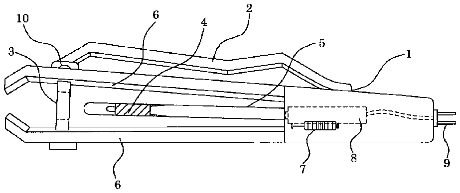
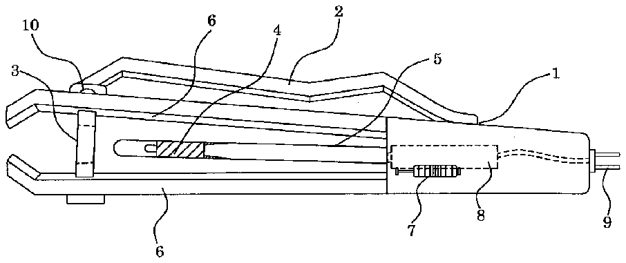
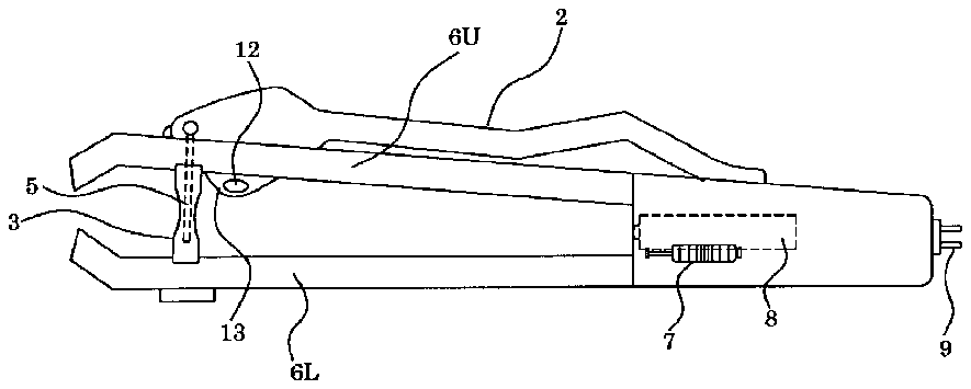
[0013] [0013]FIG. 1 is a side view of the nail/toe clipper of this invention to allow the light from the light source inserted inside of the clipper pass through.
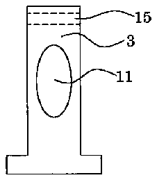
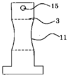
[0014] [0014]FIG. 2 is a side view of the pin of the nail/toe clipper of this invention to allow the light from the light source inserted inside of the clipper to pass through.
[0015] [0015]FIG. 3 is a front view of the pin of the nail/toe clipper of this invention to allow the light from the light source inserted inside of the clipper to pass through.
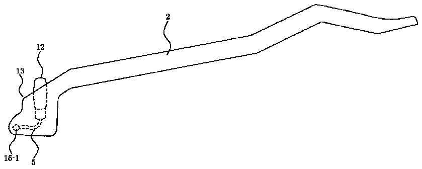
[0016] [0016]FIG. 4 is a side view of the biasing lever of another embodiment of the invention, where a light source is inserted in the front head of the lever.
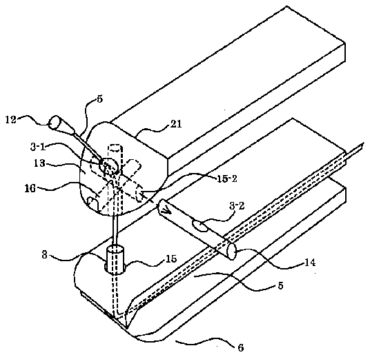
[0017] [0017]FIG. 5 is an expended drawing of the path of the wires through the lever pin and the pivot pin of the nail/toe cutter of another embodiment of this invention.
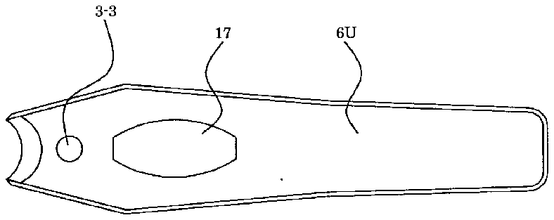
[0018] [0018]FIG. 6 is an over view of the upper spring arm having a hole for allowing the light source inserted lever of the FIG. 5 enter into the main body when not in use.
[0019] [0019]FIG. 7 is a side view the nail/toe clipper, which has light source inside of the biasing lever of the FIG. 5.
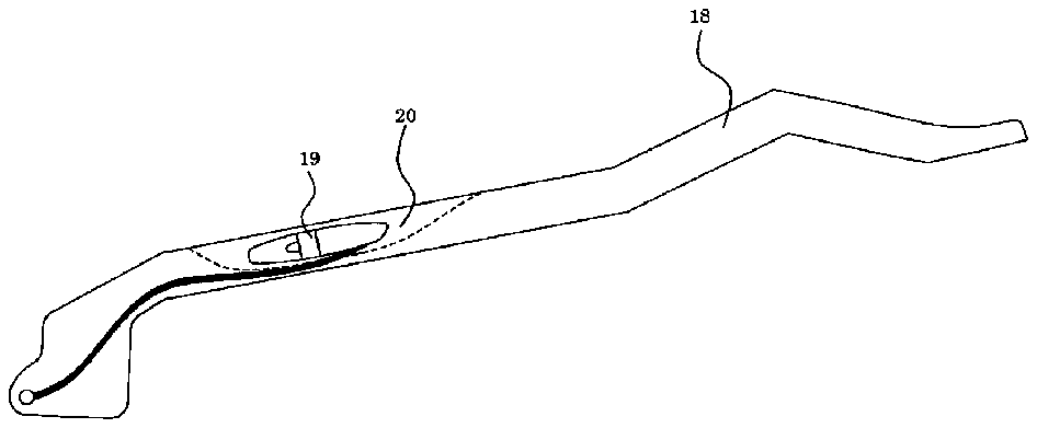
[0020] [0020]FIG. 8 is a side view of another embodiment of the biasing lever of this invention where a light source is inserted in the plate of the lever.
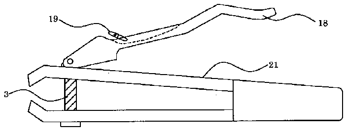
[0021] [0021]FIG. 9 is a side view of nail/toe clipper of this invention, where a light source is inserted in the plate of the lever as in FIG. 8.
[0022] [0022]FIG. 10 is a perspective drawing of the pivot pin, which is another embodiment of this invention, where a light source is inserted inside of the pin.
[0023] [0023]FIG. 11 is a side view of the nail/toe clipper of this invention having a light source inside of the pin as in FIG. 10.
[0024] [0024]FIG. 12 is a perspective view of the nail/toe clipper having a light source inserted in one of the holes ( 15 - 2 ) and ( 15 - 3 ) is not using.
[0025] [0025]FIG. 13 is a perspective view of the nail/toe clipper having a light source inserted in one of the holes ( 15 - 2 ) and ( 15 - 3 ) is in using.
[0026] [0026]FIG. 14 is a cross sectional view of another embodiment of the pivot pin of this invention where a light source is partly inserted inside of the pin.
[0027] [0027]FIG. 15 is a side view of nail/toe clipper having a light source inserted pin of FIG. 14.
[0028] [0028]FIG. 16 is a side view of lever pin for the nail/toe clipper of the FIG. 15 to allow 360-degree rotation of the lever without rotating the lower part of the pin.
[0029] [0029]FIG. 17 is an over view of the lever pin for the nail/toe clipper of the FIG. 15 to allow 360 degree rotation of the lever without rotating lower part of the pin.
[0030] [0030]FIG. 18 is an over view of the nail/toe clipper of another embodiment of this invention having light source inserted lever pin.
[0031] [0031]FIG. 19 is an over view of the nail/toe clipper of the third embodiment of this invention having light source installed through the front face (blade) of upper spring arm.
DETAILED DESCRIPTION OF THE PREFERRED EMBODIMENT
[0032] [0032]FIG. 1 is a side view of the one of the nail/toe clipper ( 1 ), where a light source ( 4 ) is installed inside the main body between the two elongated spring arms ( 6 ). The clipper ( 1 ) of this invention has a biasing lever ( 2 ), a lever pin ( 10 ), two elongated spring arms ( 6 ), a pivot pin ( 3 ), a light source ( 4 ), wires ( 5 ), on/off switch ( 7 ), a rechargeable battery ( 8 ), and a recharge plug ( 9 ). The power for the light source ( 4 ) is charged into the rechargeable battery ( 8 ) and supplied to the light source ( 4 ) via the on/off switch ( 7 ) and wires ( 5 ). The rechargeable battery ( 8 ) may be replaced by a disposable battery of “AAA” size.
[0033] [0033]FIG. 2 and FIG. 3 is a side view and a front view, respectively, of the pivot pin ( 3 ) of the nail/toe clipper of this invention to allow the light from the light source ( 4 ) inserted inside of the clipper to pass through the pivot pin ( 3 ). When a user switches on the light source ( 4 ), any pin of prior arts will make a shadow unless the pin ( 3 ) has a hole ( 11 ) at the center.
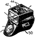
[0034] [0034]FIG. 4 is a side view of the biasing lever ( 2 ) of another embodiment of the invention where a light source ( 12 ) is inserted in the front head ( 13 ) of the lever ( 2 ). FIG. 5 is an expended drawing of the path of the wires through the lever pin ( 14 ) and the pivot pin ( 3 ) of the nail/toe cutter of this invention. The light source ( 12 ) is connected to the rechargeable battery ( 8 ) via wires ( 5 ), which pass through the lever pin ( 14 ), holes ( 3 - 1 ), ( 3 - 2 ) and the pivot pin ( 3 ). The head part ( 13 ) of the biasing lever ( 2 ) is thickened for the space of the light source ( 12 ). The groove ( 16 ) provides a space for the wires ( 5 ) to be buried therein when the nail/toe clipper is not in use. FIG. 6 is an over view of the upper spring arm ( 6 U) having a hole ( 17 ) for allowing the light source ( 12 ) inserted in the head ( 13 ) of the biasing lever ( 2 ) enter into the main body when not in use. FIG. 7 is a side view of the nail/toe clipper which has light source ( 12 ) inside of the head ( 13 ) of the biasing lever ( 2 ). The thickened head ( 13 ) and the light source ( 12 ) locate under the upper spring arm ( 6 U) when the clipper of this invention ( 1 ) is not used.
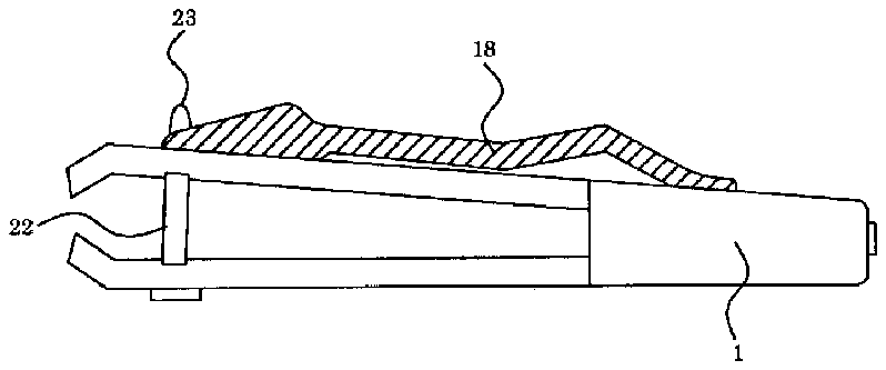
[0035] [0035]FIG. 8 is a side view of another embodiment of the biasing lever ( 18 ) of this invention where a light source ( 19 ) is inserted in a pocket ( 20 ) on the lever ( 18 ). FIG. 9 is a side view of the nail/toe clipper ( 21 ); the lever ( 18 ) of FIG. 8 is equipped thereon. Connection of the light source ( 19 ) to the battery ( 8 ) is the same as that shown in FIG. 5. In this case the wire ( 5 ) comes into the hole ( 21 ) of FIG. 5.
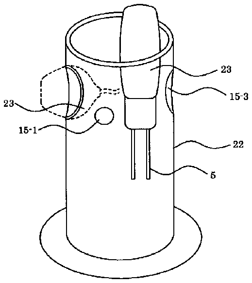
[0036] [0036]FIG. 10 is a perspective drawing of one of the embodiment of pivot pin ( 22 ) of this invention where a light source ( 23 ) is inserted inside of the pin. The light source ( 23 ) is expose to the top of the pivot pin ( 22 ). FIG. 11 is a side view of the nail/toe clipper ( 1 ) equipped with the pivot pin ( 22 ) of FIG. 10. Power to the light source ( 23 ) is supplied via the wires ( 5 ) from the power source ( 8 ), a disposable battery or a rechargeable battery.
[0037] Two additional holes, ( 15 - 2 ) and ( 15 - 3 ), are developed just below of the top end of the pivot pin ( 22 ) for engaging of the light source ( 23 ). FIG. 12 and FIG. 13 is a perspective view of the nail/toe clipper having light source ( 23 ) inserted in one of the holes ( 15 - 2 ) and ( 15 - 3 ). FIG. 12 is a perspective view of the clipper when not in use. The light source ( 23 ) faces to the body of the clipper ( 1 ). FIG. 13 is a perspective view of the clipper ( 1 ) when in use. The light source ( 23 ) faces to the front direction.
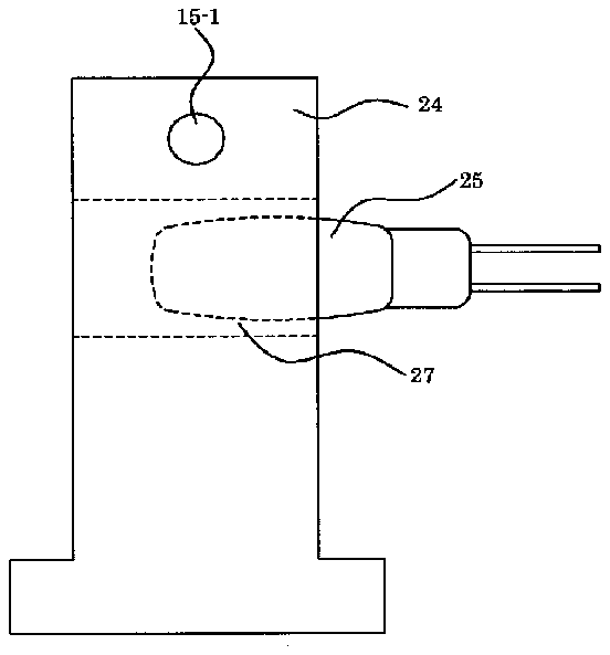
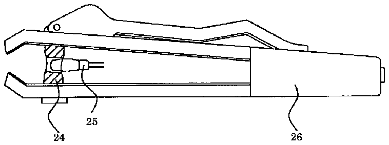
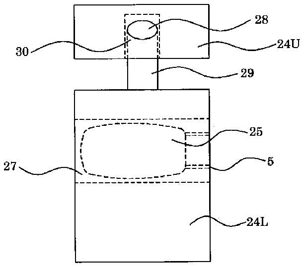
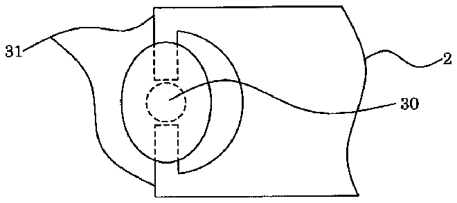
[0038] [0038]FIG. 14 is a cross sectional view of another embodiment of the pivot pin ( 24 ) of this invention where a light source ( 25 ) is partly inserted inside of the pin ( 24 ). FIG. 15 is a side view of nail/toe clipper ( 26 ) having light source inserted pin of FIG. 12. The light source ( 25 ) is inserted in a hole ( 27 ) at the center of the pivot pin ( 24 ). FIG. 16 is a side view of lever pin for the nail/toe clipper of the FIG. 15 to allow 360-degree rotation of the lever without rotating the lower part of the pin. FIG. 17 is an over view of the lever pin of FIG. 16. As shown in FIG. 15, the lower part of the pivot pin ( 24 L) should not rotate because of the light bulb ( 25 ) and wires ( 5 ). The upper part of the pivot pin ( 24 U) has a partially blocked holes ( 28 ) and ( 30 ). A neck ( 29 ), extended from the lower part of the pivot pin ( 24 L) is engaged into the hole ( 30 ). Two lever ends ( 28 ), extended from the biasing lever ( 2 ), are engaged through the holes ( 28 ) developed at the upper part of the pivot pin ( 24 U).
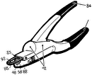
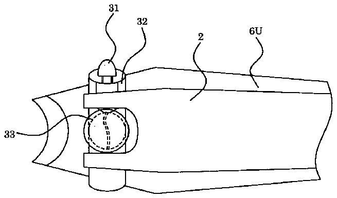
[0039] [0039]FIG. 18 is an over view of the nail/toe clipper of another embodiment of this invention having a light bulb ( 31 ) inserted lever pin ( 32 ). The lever pin ( 32 ) is a hollow tube large enough to insert a light source ( 31 ). The pivot pin ( 33 ) also is a hollow tube like shown in FIG. 10.
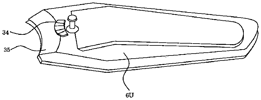
[0040] [0040]FIG. 19 is an over view of the nail/toe clipper of the third embodiment of this invention having a light bulb ( 34 ) installed through the front face (blade) ( 35 ) of upper spring arm ( 6 U).


