- 10assembly
- 11nail clippers
- 12recess
- 13side edges
- 15back edge
- 16tab
- 17bottom or floor
- 18hole
- 19upper arm
- 20lower arm
- 21joined ends
- 22upper blade
- 23lower blade
- 24blades
- 25operating lever
- 26light source
- 27handle
- 28battery
- 29switch
- 30portion
- 31tip
- 32finger
- 35intersection
- 36cutting line
- 37finger nail guides
- 39under surfaces
- 41transition portion
- 42reference character
- 43handle
- 44wafer battery
- 45wafer battery 44 enclosure
- 46switch
- 48lens
- 49nail clippers
- 50finger rest
- 51operating lever
- 52user's right hand
- 53subject's finger
- 54user's left hand
Abstract
A nail clipping assembly holds a pair of conventional nail clippers in a holder. The holder can also support a light source which is positioned close enough to a subject's finger tip to illuminate the interior of the finger tip. This exposes the intersection between a finger nail which is part of a finger and the exposed nail portion, some or all of which will be cut by the nail clippers.
Description
CROSS-REFERENCE TO RELATED APPLICATIONS
The applicants have filed a provisional application on Sep. 17, 2002, application No. 60/411,476.
BACKGROUND OF THE INVENTION
The field of the invention is nail clippers and the invention relates more particularly to an improvement to nail clippers which utilizes a source of light to illuminate the interior of the tip of a subject's finger. A problem exists especially with the cutting of an infant's or toddler's finger nails. The infant or toddler tends to pull away and move in such a way that it is very difficult to accomplish a nail clipping operation. It has been recommended that an infant's or toddler's nails be clipped while the infant or toddler is sleeping. The main difficulties in this approach is that it is typically dark when the infant is sleeping and turning on a light wakes the child.
Even in a brightly illuminated area, the intersection between the portion of the nail which extends beyond the subject's finger and that which is still part of the subject's finger is sometimes difficult to see. Several attempts have been made to illuminate the area of the cutting end of a nail end of a nail clipper. One such device is shown in U.S. Pat. No. 6,553,592, where a pair of LEDs is held outwardly from the end of the nail clipper to illuminate a target place. Another patent showing a light to illuminate the cutting area is U.S. Pat. No. 6,220,251. This device also has a magnifying glass and the light is provided by LED 34 . The light and the magnifying glass assist in the viewing of the nail clipping area whether it be for a pet or a human.
By placing the light at a significant distance from the finger nail, the result is the illumination of the exterior surface of the finger tip and nail. Such lighting does not emphasize the line between the finger nail over the finger and the extending part of the finger nail.
BRIEF SUMMARY OF THE INVENTION
The present invention is for a nail clipping assembly including a pair of nail clippers. A light source is held near the upper and lower blades of the nail clippers and positioned so that when a finger is moved so that the nail to be cut is between the blades of the nail cutter, the light source will illuminate the interior of the finger under its nail so that an intersection between the extending portion of the nail and the finger is clearly visible. Preferably, the pair of nail clippers is held in a holder which has a recess for supporting the nail clippers and which also holds batteries and a light bulb or LED. Preferably, the holder has a finger nail guide extending just below the upper blade of the nail clippers. In this way, a subject's finger nail can be raised upwardly until it contacts the finger nail guides and then moved forwardly into the space between the cutting blades of the nail clippers. The present invention also includes the ergonomic handle for holding the nail clippers so that the nail clippers can be supported by the user's palm and fingers instead of just between the fingers, as is done for conventional nail clippers.
BRIEF DESCRIPTION OF THE SEVERAL VIEWS OF THE DRAWING
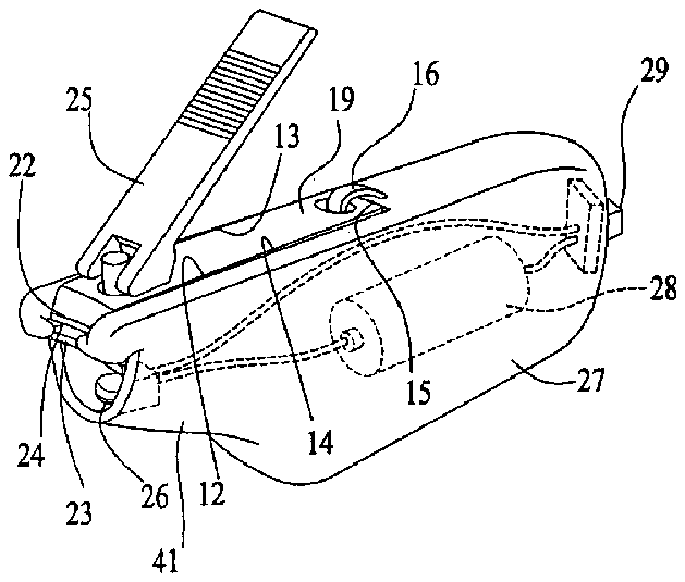
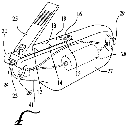
FIG. 1 is a perspective view showing the top, front and left side of the nail clipping assembly of the present invention.
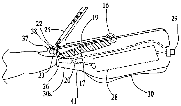
FIG. 2 is a left side view thereof partially cut away.
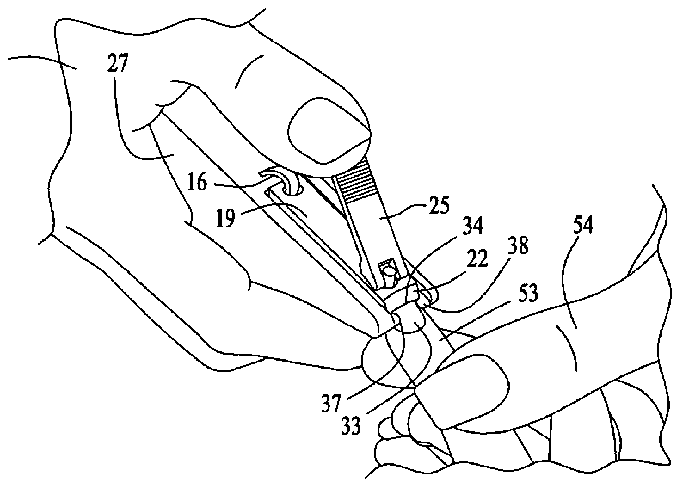
FIG. 3 is a perspective view showing a user cutting a subject's fingernail.
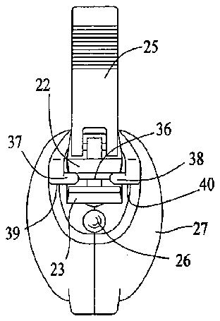
FIG. 4 is a front view thereof.
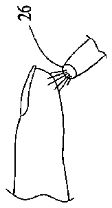
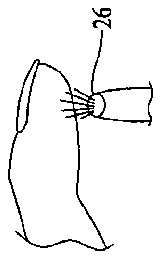
FIG. 5 is a side view of a finger and finger nail together with a light bulb of the nail clipping assembly of the present invention.
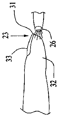
FIG. 5A is a side view of a subject's finger and a light source.
FIG. 5B is a side view of a subject's finger and a light source.
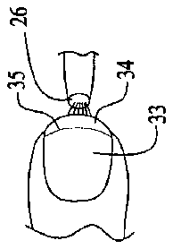
FIG. 6 is a top view of FIG. 5 .
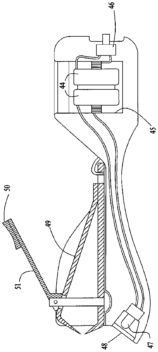
FIG. 7 is a cross-sectional view of an alternate embodiment of the nail clipping assembly of FIG. 1 .
DETAILED DESCRIPTION OF THE INVENTION
A nail clipping assembly 10 is shown in perspective view in FIG. 1 . Assembly 10span> holds conventional nail clippers 11 in a recess 12 . Recess 12 has side edges 13 and 14 and a back edge 15 . Since most conventional nail clippers have a hole near the joined ends of the nail clipper, a tab 16 will extend upwardly from the bottom or floor 17 of recess 12 and pass through the hole 18 in nail clippers 11 .
The nail clippers 11 are preferably conventional nail clippers. Such clippers have an upper arm 19 and a lower arm 20 . These arms are joined at joined ends 21 typically by a rivet not shown. As is well known, these arms are joined in a way so that an upper blade 22 and a lower blade 23 are spaced apart at the blade end 24 of the nail clippers are spaced apart. An operating lever 25 moves the upper arm downwardly so that upper blade 22 and lower blade 23 contact one another, thereby cutting a finger nail which has been inserted between them.
The handle 27 is useful as part of the assembly of the present invention for several reasons. First of all, it makes it much easier to hold nail clippers 11 . This is especially useful when trying to cut an infant's finger nails where positioning of the nail clipper is critical. Handle 27 includes a forward portion 30 a , a transition portion 41 , and a hand graspable portion 30 , which portions 30 a , 41 , and 30 are preferably rounded. The forward portion 30 a extends forward approximately to the blades 24 , is smaller in cross-section than the hand graspable portion 30 , and houses a light source 26 , such as a light bulb or LED and a battery 28 , as well as associated wiring and a switch 29 . The hand graspable portion 30 is large enough to support a user's fingers on one side and palm on the other side. This frees the user's thumb for operation of operating lever 25 in a very comfortable manner. The transition portion 41 transitions between the forward portion 30 a and the hand graspable portion 30 as shown in FIG. 2 , and cooperates with the forward portion 30 a to provide a resting place for a user's index finger proximal to and just behind the blades 24 as shown in FIG. 3 . The portion 41 is preferably a smooth upwardly and forwardly sloping transition between portions 30 a and 30 to provide a comfortable resting place for the user's index finger. Handle 27 is preferably injection molded and has provisions for opening for replacement of the battery or bulb/LED.
FIG. 3 shows a user holding the handle 27 with the user's right hand 52 and holding a subject's finger 53 with the user's left hand 54 . The subject's finger nail 33 is positioned with the aid of guides 37 and 38 .
An important feature of the present invention is the presence of light source 26 . Light source 26 performs a very different function from the light sources shown in U.S. Pat. Nos. 6,553,592 and 6,220,251. That is, the light source 26 is placed close enough to the finger tip to illuminate the inner portion of the finger tip so that it glows with an orange glow causing the nail ledge to appear dark in color. Most everyone is familiar with the effect of placing a flashlight under the palm of one's hand at night and turning it on. This causes one's hand to glow orange. This same effect is accomplished by light source 26 if it is placed near or touching the tip 31 of finger 32 . By the term “near” it is intended to mean a small fraction of an inch such as ⅛ of an inch or less. The fingernail is indicated by reference character 33 in FIG. 5 and that portion of the fingernail which extends beyond the subject's finger is indicated by reference character 34 in FIG. 6 . When the light source is placed to cause the finger tip to glow orange, the intersection 35 between that portion of the fingernail 33 over the subject's finger and the extending part of the nail 34 appears much darker and is highly visible. Therefore, the fingernails can be easily and precisely cut in dim light or even in darkness. Light source 26 guides the nail clippers to an appropriate position over the fingernail and once in position, lights the inner portion of the finger tip to facilitate the positioning of the cutting line 36 between upper blade 22 and lower blade 23 .
When used to cut the finger nails of an infant or toddler, the device of the present invention, when using a light source near the finger tip, permits the caregiver to cut the infant's or toddler's finger nails at night in dimly lit conditions while the infant or toddler is sleeping without the necessity of turning on the room light or providing any other source of external light. While the above discussion has used the word “finger,” it is to be understood that the device can equally be used on toenails.
Another important feature of the present invention is the presence of finger nail guides 37 and 38 . These guides have under surfaces 39 and 40 , as shown in FIG. 4 , which are aligned slightly below the lower edge of upper blade 23 . In this way, as shown best in FIG. 3 , a subject's finger nail can be brought upwardly until it contacts the under surfaces 39 and 40 and then moved inwardly toward the cutting edges until the clipper is in a desired position. Preferably, the finger nail guides 37 and 38 are separated so that most of the extending part 34 of the finger nail is visible.
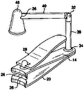
The orientation of the light source 26 is not critical as long as it causes the finger tip to glow orange in subdued light. It may be aligned outwardly from the tip of the finger shown in FIG. 5 or positioned at an angle as shown in FIG. 5A . It could also be placed under the finger as shown in FIG. 5B . It is easy to determine in subdued light whether light placement causes the finger to glow orange or simply lights the external part of the finger. It is generally preferable that the light be below the level of the finger nail.
An alternate embodiment of the nail clipping assembly is shown in FIG. 7 and indicated by reference character 42 . This embodiment has a handle 43 including a wafer battery 44 enclosure 45 and a switch 46 . A bulb or LED 47 is covered with a lens 48 . The nail clippers 49 include a finger rest 50 on operating lever 51 . Bulb 47 is aimed toward a finger tip at a 45° angle.
While the device has been shown and described with the presence of a light, the hand graspable handle itself is useful even if the light is not turned on or not used. The ease with which the nail clippers can be positioned is greatly enhanced by handle 30 .
The present embodiments of this invention are thus to be considered in all respects as illustrative and not restrictive; the scope of the invention being indicated by the appended claims rather than by the foregoing description. All changes which come within the meaning and range of equivalency of the claims are intended to be embraced therein.


