- 21 or
- 10illuminated nail trimmer unit
- 12handgrip
- 14clipper
- 16light source
- 18illumination controller
- 20aperture
- 21spring biased button
- 24generate light
- 26top shell
- 27side panels
- 28bottom shell
- 30top shell
- 31nail cutter
- 32stationary member
- 33bottom plate
- 34jaw
- 35movable member
- 36top plate
- 37bottom jaws
- 38cutter squeezer
- 39curved cutting edge
- 40upright post
- 41aperture
- 42actuator
- 45aperture
- 51light bulbs
- 52second light bulb
- 54battery
- 56circuit
- 58open-biased switch
- 64rigid upper frame
- 65soft upper skin
- 67intermediate portion
- 68forward portion
- 70intermediate portion
- 71screw
- 72central aperture
- 74rigid lower frame
- 78forward portion
- 82exterior surface
- 83textured grip surface
- 84include raised laterally extending ribs
- 101thumb pressure
- 130pivot lever
- 132thumb pad
- 134distal end
- 138opening
- 154battery compartment
- 156cross-shaped opening
- 905leds
- 920resistance elements
- 945battery
- 950capacitor
- 955switch
- 960diodes
Abstract
An illuminated nail trimmer unit includes a handgrip formed to include a top shell and bottom shell, a clipper including a nail clutter and a nail cutter actuator that may be positioned either in a storage position or an operative position, and a light source.
Description
[0001] This application claims priority under 35 U.S.C. § 119(e) to U.S. Provisional Application Ser. No. 61/036,633, filed Mar. 14, 2008, which is expressly incorporated by reference herein.
BACKGROUND
[0002] The present disclosure relates to nail clippers. More particularly, the present disclosure relates to nail clippers with lights.
SUMMARY
[0003] An illuminated nail trimmer unit in accordance with the present disclosure includes a handgrip, a clipper, an illumination controller, and a light source. The clipper includes a nail cutter and a nail cutter actuator.
[0004] In Illustrative embodiments, the clipper actuator may be positioned either in a storage position or an operative position. When the clipper actuator is positioned in the operative position, the illumination controller is operated to turn on the light source. When the actuator is positioned in the storage position, the illumination controller is operated to turn off the light source. Thus, the nail trimmer unit provides an illuminated light source to aid a user when the user operates the clipper with a single hand.
[0005] In illustrative embodiments, the illumination controller includes a spring-biased button positioned in the handgrip such that, when the clipper actuator is positioned in the storage position, the button is depressed to maintain the light source off. When the clipper actuator is positioned otherwise, the button is released thereby turning on the light source.
[0006] In illustrative embodiments, the handgrip includes a top shell and bottom shell, which both have a rigid frame covered at least partially by a soft skin.
[0007] In illustrative embodiments, the illumination controller includes an open biased switch having a movable contact, a stationary contact, and a contact spring section. When the clipper actuator is in a storage position, pressure is applied to the contact spring section, causing the movable contact to be out of contact with the stationary contact and turn off the light source. When the clipper actuator is not in the storage position, the contact spring section causes the movable contact to be in contact with the stationary contact and thereby operates the illumination controller to cause the light source to turn on.
[0008] In illustrative embodiments, the illumination controller also includes circuitry that enables the light source to turn off after a period of time, even though the clipper actuator is not in a storage position, to ensure that a battery included in the illuminated nail trimmer unit is not accidentally drained of power by leaving the clipper actuator in an operative position.
[0009] Additional features of the present disclosure will become apparent to those skilled in the art upon consideration of illustrative embodiments exemplifying the best mode of carrying out the disclosure as presently perceived.
BRIEF DESCRIPTION OF THE DRAWINGS
[0010] The detailed description particularly refers to the accompanying figures in which:
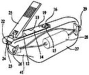
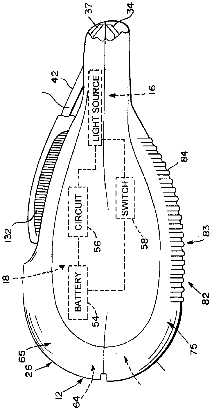
[0011] FIG. 1 is a side elevation view of an illuminated nail trimmer including a handgrip formed to include a top shell and bottom shell, a clipper coupled to the handgrip and in a storage position, and showing in phantom a light source and an illumination controller including a switch, battery, and circuit for activation of the light source;
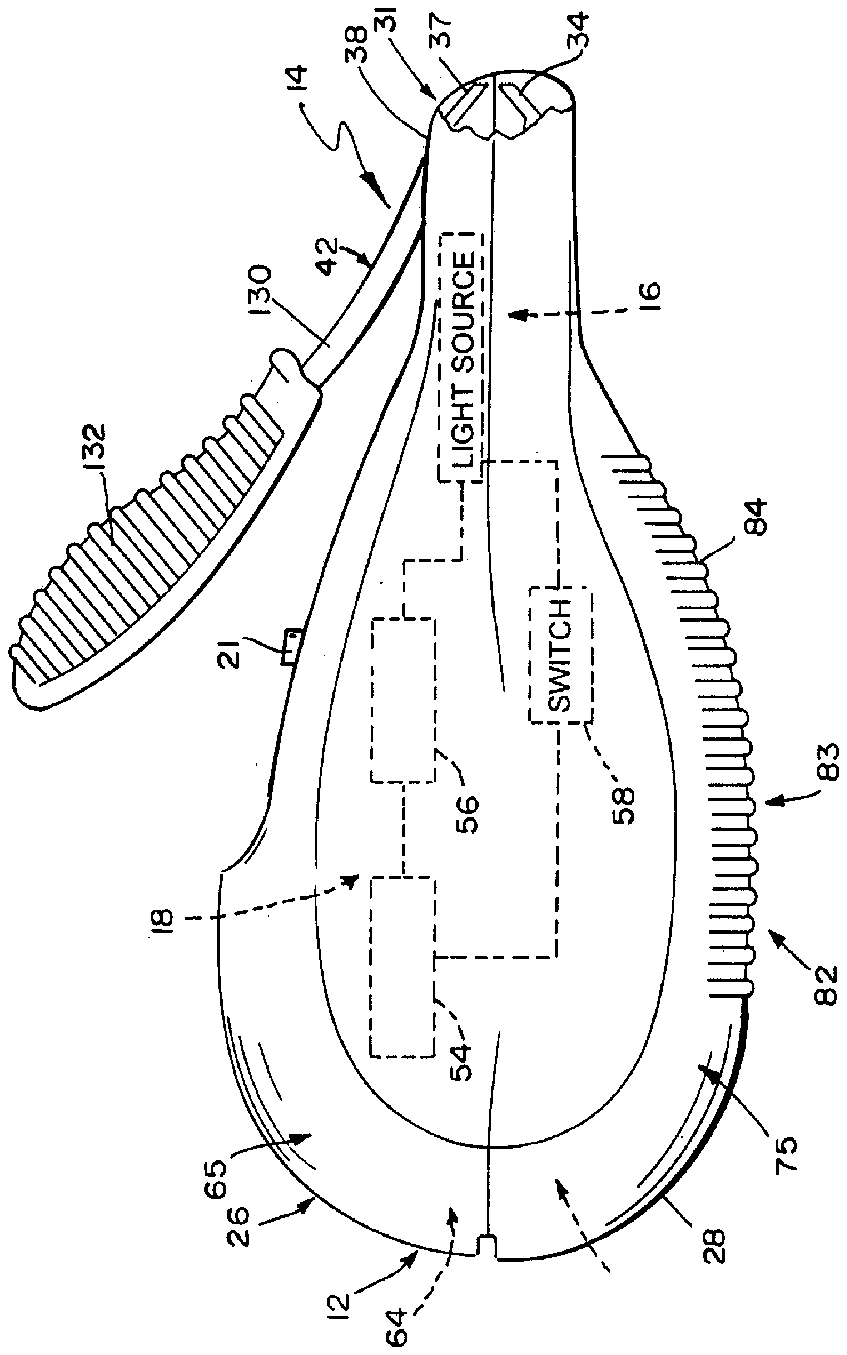
[0012] FIG. 2 is a side elevation view of an illuminated nail trimmer including a handgrip formed to include a top shell and bottom shell, a clipper coupled to the handgrip and in an operative position, and showing in phantom a light source and an illumination controller including a switch, battery, and circuit for activation of the light source;
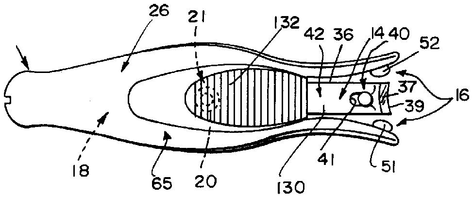
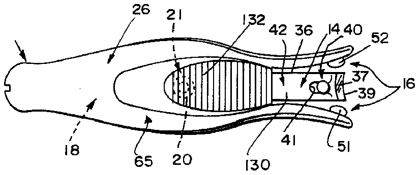
[0013] FIG. 3 is a top elevation view of the illuminated nail trimmer of FIG. 1 or 2 showing the top shell and the top of the clipper and showing that the light source includes light bulbs positioned to lie on either side of the clipper;
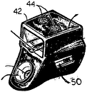
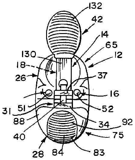
[0014] FIG. 4 is a front elevation view of the illuminated nail trimmer of FIG. 2 showing the front of the top shell, bottom shell, clipper formed to include an upper jaw and lower jaw, and light bulbs positioned to lie in proximity to the upper and lower jaws;
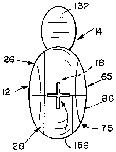
[0015] FIG. 5 is a rear elevation view of the illuminated nail trimmer of FIG. 2 showing that the top shell and bottom shell cooperate to form a cross-shaped access opening;
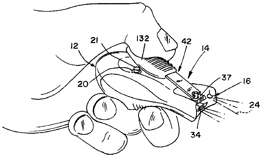
[0016] FIG. 6 is a perspective view of the illuminated nail trimmer of FIG. 2 showing the light source activated prior to the user using the clipper;
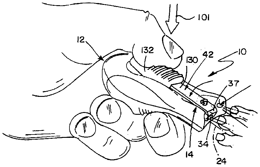
[0017] FIG. 7 is a perspective view of the illuminated nail trimmer of FIG. 2 showing the light source activated during the user using the clipper;
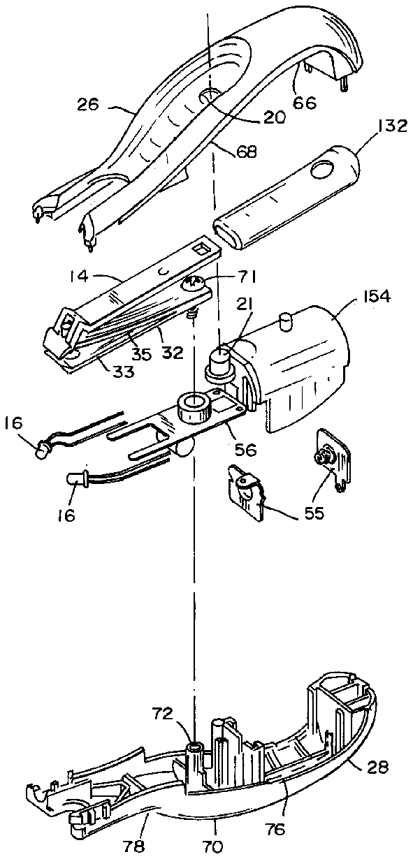
[0018] FIG. 8 is an exploded perspective assembly view of the illuminated nail trimmer of FIGS. 1 and 2 showing that a switch included in the illumination controller includes a stationary contact and a movable contact and also suggesting placement of the clipper, switch, circuit, and light source in the interior region of the handgrip; and
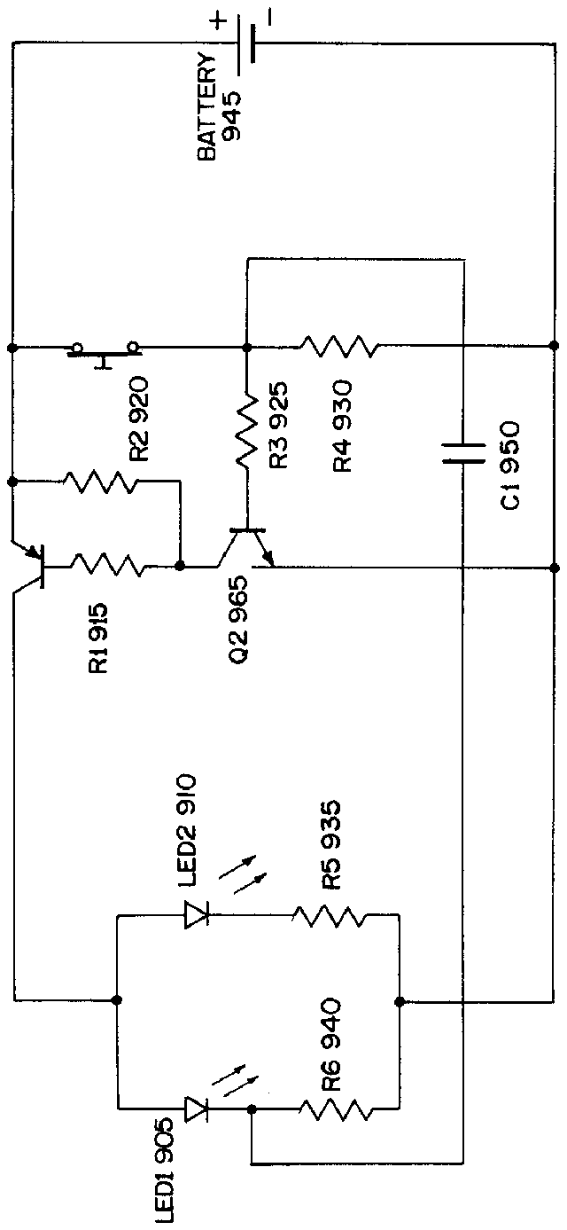
[0019] FIG. 9 is an example of one potential circuit configuration that may be included in the illumination controller.
DETAILED DESCRIPTION
[0020] An illuminated nail trimmer unit 10 includes a handgrip 12 , a clipper 14 coupled to handgrip 12 , a light source 16 , and an illumination controller 18 associated with handgrip 12 and light source 16 as suggested somewhat diagrammatically in FIG. 1 and illustratively in FIG. 9 . As illustrated in FIG. 2 , a spring biased button 21 is provided in an aperture 20 (see FIG. 3 ) included in the handgrip 12 ; when the spring biased button 21 is in its biased position (i.e., protruding from the handgrip 12 ), a switch (explained in detail with reference to FIG. 9 ) is operated to energize light source 16 to generate light 24 and shine light 24 on fingers of a child or other person before nails on those fingers are trimmed using clipper 14 as suggested in FIGS. 6-7 .
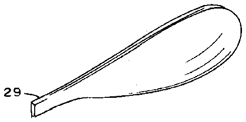
[0021] Handgrip 12 includes a top shell 26 , a bottom shell 28 and side panels 27 , 29 (illustrated in FIG. 8 ). Top and bottom shells 26 mate to form an interior region containing illumination controller 18 and a portion of clipper 14 .
[0022] As suggested in FIG. 5 , clipper 14 includes a nail cutter 31 and a cutter squeezer 38 . Nail cutter 31 includes a lower stationary member 32 including a bottom plate 33 and a bottom jaw 34 and an upper movable member 35 including a top plate 36 and a top jaw 37 . Cutter squeezer 38 is configured to squeeze nail cutter 31 by, for example, urging movable member 35 (illustrated in FIG. 8 ) downwardly toward stationary member 32 to move top and bottom jaws 37 , 34 relative to one another to a closed nail-trimming position shown, for example, in FIG. 7 . Each of top and bottom jaws 37 , 34 includes a curved cutting edge 39 as shown in FIG. 3 .
[0023] In an illustrative embodiment, cutter squeezer 38 includes an upright post 40 and a pivotable actuator 42 as shown in FIG. 3 . Upright post 40 is rooted to bottom plate 33 and arranged to extend upwardly through an aperture 45 formed in bottom plate 33 and an aperture 41 formed in top plate 36 .
[0024] In use, the clipper actuator 42 is always moved out of a storage position (illustrated in FIG. 2 ) by a user to cause illumination controller 18 to energize light source 16 to shine light 24 toward fingernails to be trimmed before the actuator 42 is moved to cause movement of top and bottom jaws 37 , 34 to the closed nail-trimming position. Thus, it should be understood that actuator 42 is a pivotable actuator that can be pivoted about the upright post 40 and lifted and rotated so as to be inverted and in a position for operation of the actuator 42 in cooperation with the nail cutter 31 .
[0025] When the actuator 42 is in the storage position, actuator 42 is positioned to depress a spring biased button 21 protruding from an aperture 20 in the handgrip 12 . While the spring biased button 21 is depressed, the illumination controller 18 circuitry (described in detail with reference to FIG. 9 ) controls the light source to be turned off. When the clipper actuator is not in the storage position, the illumination controller 18 controls the light source to turn on.
[0026] Actuator 42 can be moved downwardly, as suggested in FIG. 7 , in response to downward application of thumb pressure 101 to actuator 42 by a user to cause top and bottom jaws 37 , 34 to move toward one another to the closed nail-trimming position. However operation of actuator 42 in this manner does not interfere with the spring biased button 21 . Thus, light 24 always shines on fingernails when they are being trimmed by clipper 14 when using illuminated nail trimmer unit 10 .
[0027] Light source 16 is turned off automatically once the user places the actuator 42 in the storage position as illustrated in FIG. 1 .
[0028] Light source 16 is coupled to the top shell 26 and/or the bottom shell 28 and arranged to lie near the top and bottom jaws 37 , 34 of clipper 14 as suggested in FIGS. 3 and 4 . In an illustrative embodiment, light source 16 includes a first light bulb 51 located on one side of top jaw 37 and a second light bulb 52 located on an opposite side of top jaw 37 as suggested in FIGS. 2 and 3 . Both light bulbs 51 , 52 are coupled to illumination controller 18 as shown, for example, in FIG. 5 . These light bulbs 51 , 52 may be implemented as Light Emitting Diodes (LEDs).
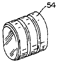
[0029] Illumination controller 18 includes a battery 54 , a circuit 56 , and an open-biased switch 58 associated with spring biased button 21 as suggested in FIGS. 2 and 6 . In an illustrative embodiment, the open-biased switch includes a stationary contact and a movable contact. Thus, switch 58 may include a stationary contact and a movable contact normally separated from the stationary contact wherein the movable contact is arranged to be moved upwardly to engage stationary contact to close the open-biased switch 58 when the spring biased button 21 is in the biased position (i.e., protruding from the handgrip 12 ) so as to cause the battery 54 and circuit 56 to cooperate to energize light source 16 and generate light 24 . When the spring biased button 21 is depressed by the actuator 42 (i.e., in the storage position), the stationary and movable contacts of the open-biased switch 58 are separated. Thus, the open-biased switch 58 is open so as to disable cooperation of the battery 54 and the circuit 56 and turn off the light source 16 .
[0030] In an illustrative embodiment, top shell 26 of handgrip 12 includes an interior rigid upper frame 64 and an exterior soft upper skin 65 overmolded or otherwise mounted onto an exterior surface of rigid upper frame 64 . A rearward portion 66 of rigid upper frame 64 mates with battery compartment 154 as suggested in FIG. 8 . A forward portion 68 of rigid upper frame 64 and a forward portion of soft upper skin 65 mate with top plate 36 of clipper 14 when clipper 14 is mounted in an interior region of handgrip 12 as suggested, for example, in FIG. 8 . An intermediate portion 67 of rigid upper frame 64 is arranged to interconnect rearward and forward portions 66 , 68 of rigid upper frame 64 as suggested in FIGS. 1 and 8 .
[0031] In an illustrative embodiment, bottom shell 28 of handgrip 12 includes an interior rigid lower frame 74 and an exterior soft lower skin 75 overmolded or otherwise mounted onto an exterior surface of rigid lower frame 74 . A rearward portion 76 of rigid lower frame 74 mates with battery compartment 154 as suggested in FIG. 8 . A forward portion 78 of rigid lower frame 74 is arranged to underlie and mate with and support bottom plate 33 of clipper 14 as shown in FIG. 7 .
[0032] A central aperture 72 is formed in intermediate portion 70 of rigid lower frame 74 of bottom shell 28 of handgrip 12 as shown best in FIG. 8 . The central aperture 72 may include a female threaded interior that is mateable with screw 71 of the clipper 14 so as to secure the clipper 14 to the bottom shell 28 , as shown, for example, in FIG. 8 .
[0033] An exterior surface 82 of soft lower skin portion 75 has a textured grip surface 83 formed to include raised laterally extending ribs 84 as shown, for example, in FIGS. 1 , 2 , and 4 . In an illustrative embodiment, soft lower skin 76 is made of a plastics material.
[0034] As suggested in FIGS. 2-4 and 8 , pivotable actuator 42 of clipper 14 includes a pivot lever 130 coupled to an upright post 40 and a thumb pad 132 coupled to a distal end 134 of pivot lever 130 . Thumb pad 132 is made of a textured rubber or plastics material molded or fitted over an outer end of pivot lever 130 in the illustrated embodiment.
[0035] Pivot lever 130 can be pivoted in a counterclockwise direction in response to application of pressure 101 to thumb pad 132 to move top plate 36 toward bottom plate 33 to move jaws 37 , 34 toward one another to assume the closed nail-trimming position.
[0036] A user operates cutter squeezer 38 of clipper 14 as suggested in FIG. 7 to move top and bottom jaws 37 , 34 to assume the nail-trimming closed position. Light source 16 has already been energized to generate light 24 based on the positioning of the actuator 42 in an operative position before the user operates cutter squeezer 38 of clipper 14 .
[0037] With light source 16 on, a user can now see the fingernails of a child. Next, the user positions handgrip 12 so that the child's nail is between upper jaw 37 and lower jaw 34 of nail cutter 31 . The user then applies strong thumb pressure 101 in a downward direction onto actuator 42 as shown, for example, in FIG. 7 .
[0038] As suggested in FIG. 7 , the user applies downward pressure 101 to thumb pad 132 so as to cause pivot lever 130 to pivot about the pivot axis orthogonal to the upright post 40 and, in turn, apply a downward force to top plate 36 and an opposite upward force to cause bottom plate 33 to move upwardly toward top plate 36 . The downward force applied to top plate 36 of nail cutter 31 and the upward force applied to bottom plate 33 is transferred to top and bottom jaws 37 , 34 , causing them to move toward one another to assume the closed nail-trimming position. Once pressure 101 is no longer applied to thumb pad 132 , then top and bottom plates 36 , 33 spring apart to resume their original positions shown, for example, in FIG. 6 .
[0039] Battery 54 is sandwiched between rigid lower frame 74 and rigid upper frame 16 and arranged to rest in battery compartment 154 in an interior space formed in rigid lower frame 74 as suggested in FIG. 7 .
[0040] Although the circuit 56 included in the illumination controller 18 may be configured in any number of ways, FIG. 9 illustrates one example of circuitry that may be used to provide the functionality of the illumination controller 18 . As illustrated in FIG. 9 , the circuit 56 may include a pair of LEDs 905 , 910 (which correspond to the light source 16 illustrated in other figures). Additionally, the circuit 56 may include a plurality of resistance elements 920 - 940 provided in combination with a battery 945 (corresponding to battery 54 illustrated in other figures), capacitor 950 , switch 955 and a plurality of diodes or transistors 960 , 965 . The resistance elements 920 - 940 may be provided to balance the circuit 56 based on operation of the LEDs 905 - 910 and charging of the capacitor 950 (explained herein).
[0041] The switch 955 is coupled to, actuated by the button 21 illustrated in FIG. 2 . Thus, as explained above, when the nail actuator 42 is in a storage position, the button 21 is depressed, thereby eliminating power to the LEDs 905 , 910 provided by battery 945 . However, when the button 21 is released and allowed to return to its spring-biased state of protruding from the handgrip 12 , the switch 955 is operated to provide power to the LEDs 905 , 910 .
[0042] In the circuit configuration illustrated in FIG. 9 , the power is provided via capacitor 950 which is charged by the battery 945 and, when fully charged, turns on diodes 960 , 965 . This operation of diodes 960 , 965 then alters the circuit configuration such that the capacitor 950 provides power to the LEDs 905 , 910 until power dissipates to an unusable level in the capacitor 950 . This configuration provides an automatic shut off feature that enables the light source 16 (i.e., 905 , 910 in FIG. 9 ) to be turned off after a period of time, e.g., four minutes, even though the clipper actuator is not in a storage position. This automatic shut off feature may ensure that the battery included in the illuminated nail trimmer unit is not accidentally drained of power by leaving the clipper actuator in an operative position.
[0043] An additional optional feature is shown best in FIG. 5 and provides a cross-shaped opening 156 is positioned at the rear of the handgrip 12 . Opening 138 is defined by a slot provided between the top shell 30 and bottom shell 32 to provide an aperture for inserting an emery board so as to use the handgrip 12 as an emery board holder and improve ease of use of emery boards.


