
- 3references cited united states patents
- 10improved clipper assembly
- 12clippers
- 14lens element
- 15arms
- 16arms
- 17..b26b
- 18handle portions
- 20pivot portions
- 22pivot portions
- 23blade
- 24blade portions
- 26blade portions
- 28knurled outer gripping surfaces
- 30inner surface
- 32leaf spring
- 34leaf spring
- 36pivot
- 38screw
- 40slot
- 42projecting finger
- 44cutting edges
- 46concavity
- 48concave lower surface
- 50outer edge
- 52convex upper surface
- 54concave lower surface
- 507r ..30/26 x element for toenail clippers
- 5601972 54] protective magnifying
- 6201972 54] protective magnifying
- 733r ..30/26 x element for toenail clippers
Abstract
A clipper device such as a toenail clippers is provided with a hollow dome-shaped element serving as a magnifying lens and rigidly secured to the outer edge of one of the clipper blades. The lens is wide enough to cover both blades when their cutting edges are in abutting position, thus allowing the user to obtain a close magnified view of what he is cutting, with the domeshaped element acting as a barrier to prevent pieces of clipped nail from being propelled into the face of the user.
Description
United States Patent Steinman 1 4 1 Aug. 1, 1972 54] PROTECTIVE MAGNIFYING 2,620,560 12/1952 Bahr ..30/26 x ELEMENT FOR TOENAIL CLIPPERS 2,733,507 2/1956 Dangelo ..30/123 X Charles Steinman, 161 Lawrence St., Mount Vernon, NY. 10552 Filed: March 22, 1971 Appl. No.: 126,608
Inventor:
U.S. Cl. ..30/28, 30/123, 350/244 Int. Cl. ..B26b 17/04 Field of Search ..30/2628, 123,
References Cited UNITED STATES PATENTS 3/1913 Sullivan ..7/5.4 X 1/1932 l-lunsaker et a1. ..350/244 X Primary Examiner-Robert C. Riordon Att0meyEdward F. Levy [5 7] ABSTRACT A clipper device such as a toenail clippers is provided with a hollow dome-shaped element serving as a magnifying lens and rigidly secured to the outer edge of one of the clipper blades. The lens is wide enough to cover both blades when their cutting edges are in abutting position, thus allowing the user to obtain a close magnified view of what he is cutting, with the dome-shaped element acting as a barrier to prevent pieces of clipped nail from being propelled into the face of the user.
4 Claims, 6 Drawing Figures PATENTEDAUQ' I I972 INVENTOR. CHARLES STEINMAN ATTOR PROTECTIVE MAGNIFYING ELEMENT FOR TOENAIL CLIPPERS This invention relates to improvements in clippers for toenails or the like, and in particular to toenail clippers of the type used in hospitals and doctors offices.
It is common practice for doctors and nurses to cut the fingernails and toenails of patients who have suffered injury or undergone surgery in the vicinity of the nails, or who are incapable of cutting their own nails. For this purpose, a heavy-duty nail clipper is employed, and the doctor or nurse must observe the nail closely during the cutting operation in order not to injure closely patent.
One of the major difficulties in utilizing the clippers is the difficulty in viewing the clipper blades for proper positioning of the clipper with relation to the nails, particularly where the surrounding area is damaged and is tender. Another problem in using the clippers is that after the nail is clipped, the shearing force applied often causes the clipped-off piece of nail to be propelled a significant distance so that it strikes the face of the user and sometimes lodges in his eye.
Accordingly, it is among the principal objects of the present invention to provide a protective magnifying element for toenail clippers which will allow the user to see an enlarged view of the portion of nail which he is clipping, allowing a more positive and correct cut, in less time.
Another object of the present invention is to provide a protective element, which will act as a barrier to prevent the cut nail from flying outwardly, away from the clipper and possibly striking the face of the user.
Still another object of the present invention is to provide an improved clipper of the character described which will allow much more efficient rapid use thereof, by removing the element of anxiety during the clipping process.
A further object of the present invention is to provide an improved protective magnifying element for toenail clippers which will be simple and inexpensive to manufacture, and yet be durable to a high degree in use.
SUMMARY OF THE INVENTION In accordance with the present invention there is provided in a clipper device, a protective magnifying element. The clipper device generally consists of two pivoted arms terminating in blade portions having respective cutting edges which are movable between an open, separated position and a closed, cutting position in which the cutting edges abut each other. The magnifying element is secured to one of the blade portions and moves therewith toward and away from the other blade portion. The element has a convex upper surface and a concqve lower surface define a dome-shaped body which at least partially overlies the space between the separated cutting edges in the open position thereof so that the user may obtain a magnified view of the cutting edges and the nail or other article being cut. In the closed, abutting position of the cutting edges, the magnifying element is substantially centered thereon with the dome-shaped body providing an enclosure for containing the cut-ofi pieces of the article being cut, and for preventing said pieces from being propelled away from the clipper device.
It is understood that while this invention is primarily directed to improvement in toenail clippers, it is also adaptable to clippers for fingernails, clippers for animals, and also clippers used for technical purposes, such as wire clippers.
Additional objects and advantages of the present invention will become apparent during the course of the following description when taken in connection with the accompanying drawings, in which:
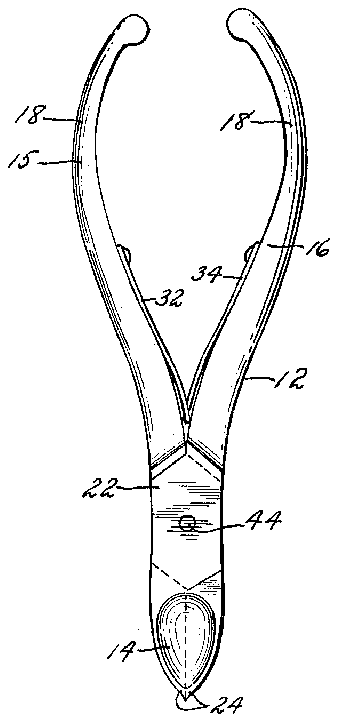
FIG. 1 is a top plan view of a toenail clipper incorporating the present invention, with the blades in closed, abutting position, and the leaf spring under tenslon;
FIG. 2 is a side elevational view thereof;
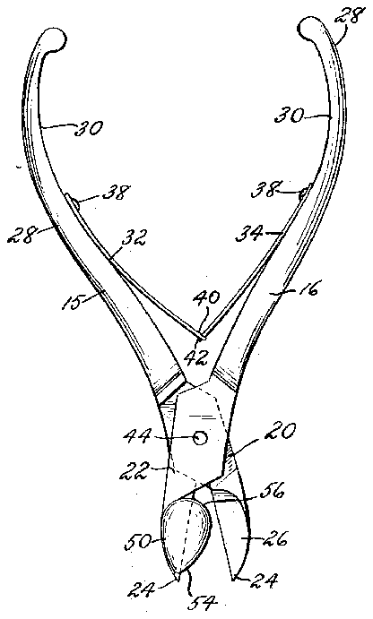
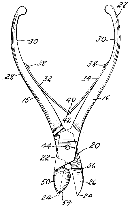
FIG. 3 is a top plan view similar to FIG. 1, but showing the clipper blades in open position;
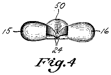
FIG. 4 is a front elevational view of the clippers in the closed position shown in FIG. 1;
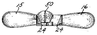
FIG. 5 is a front elevational view of the clippers in the open position of FIG. 3; and
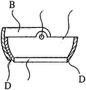
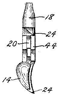
FIG. 6 is a side elevation view of the lower portion of the clippers, similar to FIG. 2, but with the blades in open position.
Referring in detail to the drawings, and more particularly to FIG. 1, there is shown an improved clipper assembly 10 which generally comprises a pair of standard nail clippers 12, provided with a protective magnifying element 14 in accordance with the present invention.
The nail clippers may be of any standard construction, and the clippers 12 illustrated herein is a conventional and well-known type distributed by medical supply houses for use by doctors, Podiatrists and the like. The clippers 12 has a pair of arms 15 and 16 including respective handle portions 18, centan>rally located pivot portions 20, 22, and front blade portions 24, 26. The handle portions 18 have knurled outer gripping surfaces 28 which provide a secure hand grip. The arms 15 and 16 are pivotally secured together by a pivot 36 passing through the pivot portions 20, 22.
On the inner surface 30 of the handle portion 18 of each arm 15 and 16, the end of a respective leaf spring 32, 34 is secured by a screw 38. At its free end, leaf spring 32 has a slot 40 which receives a projecting finger 42 at the free end of leaf spring 34. Interengagement of the free ends of the leaf springs 32, 34 occurs when the arms reach the position shown in FIGS. 3 and 5, and thereafter further force applied to handles 18 to close the arms 15 and 16 will cause tension to develop between the engaged leaf springs.
In the type of clippers 12 illustrated herein, the blade portions 24, 26 each have a cutting edge 44 defined by a concave upper surface 46 and a concave lower surface 48 shaped to simulate the general curvature of the toenail of an average user. It will be seen in FIG. 1, that when the blade portions 24, 26 are brought together in closed or clipping position with the cutting edges 44 in abutment with each other, the concave upper surfaces 46 thereof come together to form an elliptical concavity on the upper surface of the blade portions.
The nail clipper structure heretofore described is conventional and well known. In accordance with the invention herein, the nail clipper is also provided with the protective magnifying element 14 which serves the dual purposes of acting as a shield to stop the outward projection of clipped nail portions, as well as to magnify and present an improved view of the blades and nail during the clipping operation. The magnifying element has an elliptical shape, slightly larger in overall area then the aforementioned concavity 46, 46 in the upper surface of the blade portions 24 and 26. As shown in FIGS. 2, 4, 5 and 6, the element 14 is dome-shaped, having a convex upper surface 52 and a concave lower surface 54. The element 14 may be made of glass or transparent rigid plastic, and constitutes a domed, hollow magnifying lens.
One edge portion of the lens element 14 is secured to the blade 23, along the outer edge 50 of the latter, by any suitable means such as cementing, fusing or the like. In this mounted position, the'lens element 14 will move with the blade 24 between the open position of FIG. 3 and the closed position of FIG. 1. When the clippers is in the open position of FIG. 3, the lens element 14 partially overlies the space between the separated cutting edges 44 so that the user may view the nail to be cut through the lens element and properly position the blades with relation to the nail Thus, even where the cutting area is sensitive, the magnified view will minimize pain or injury to the patient.
During the cutting operation, as the clippers are brought to their closed position of FIG. 1, the lens element 14 is moved toward the opposite blade 26 until the cutting edges 44 come into abutment to sever the nail. In this final position, the lens element 14 is located in registry with the concavity 46, 46 in the upper surface of blade portions 24 and 26. The lens element 14 thus presents a hollow dome overlying said concavity so that any nail portion severed during the clipping operation will be contained within the enclosure formed by said concavity and the interior of the lens element, and cannot fly out to strike the user. It will thus be appreciated that the user can keep his face close to the clippers, to properly view the nail and blades, without fear that the cut nail portion will strike his face or lodge in his eye. In addition, the lens element serves as an enclosure to hold the cut-off nail pieces, which can be dropped out individually into a receptacle when the blades are opened after each cutting stroke.
As previously indicated, while the invention is particularly directed towards toenail clippers, it also finds use in connection with other types of clippers where it is necessary to view the section to be cut carefully, and where it is desired to provide a barrier to prevent cut pieces of materials cut from being propelled into the face of the user. Since the lens element is always of hollow, dome-shaped form, it may be used with other types of toe-nail or finger-nail clippers, in each instance serving as an enclosure to contain the cut-off pieces. While there has been described and illustrated a preferred embodiment of the present invention, it is apparent that numerous, omissions, changes and additions may be made in such embodiment without departing from the spirit and scope of the invention.
What is claimed is:
1. In a clipper device having pivoted arms terminating in blade portions having cutting edges movable between an open, separated position and a closed, cutting position in which the cutting edges abut each other, a protective magnifying element secured to one of the blade portions and movable therewith toward and away from the other blade portion, said magnifying element having a convex upper surface and a concave lower surface defining a dome-shaped body which at least partially overlies the space between the separated cutting edges in the open position thereof, whereby said cutting edges and the article being cut may be viewed therethrough, said magnifying element being substantially centered above the abutting cutting edges in the closed position thereof, with the dome-shaped body and blade portions providing an enclosure for containing the cut-off pieces of the article being cut and for preventing said pieces from being propelled away from said clipper device.
2. A clipper device according to claim 1 in which the blade portions of said clipper device have respective concave upper surfaces continuous with said cutting edges, said concave upper surfaces defining a concavity on the upper surface of said blade portions when said cutting edges are in abutment in the closed position thereof, the dome-shaped body of said magnifying element being sized to overlie and completely cover over said concavity in the closed position of said cutting edges.
3. A clipper device according to claim 2 in which said magnifying element is secured along one edge to the outer edge of one said blade potions remote from said other blade portion.
4. A clipper device according to claim 3 in which said concavity on the upper surface of the blade portions is substantially eliptical and said magnifying element is so shaped and positioned that its lower edge lies within the confines of said concavity in the closed position of said cutting edges.


