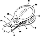
- 10safety clipper
- 13filed
- 14blade
- 16lever
- 18shaft
- 22sharp cutting edge
- 24ledge
- 26top face
- 28front face
- 30cam feature
- 32groove
- 40nail
- 42finger
- 180lever 16 may be rotated
Abstract
An apparatus for safely clipping nails comprises a blade/base assembly, a lever, and a shaft. The blade/base assembly comprises a blade incorporating a sharp cutting edge, a base incorporating a ledge having a front face for aligning the tool to the nail and a top face for supporting the nail, and a rivet to fix said blade to said base. The lever is designed to actuate the apparatus, having a fixed end, an unconstrained end, and a cam. The fixed end is mechanically fixed to said blade/base assembly by means of a shaft designed to place said blade/base assembly into a spring-loaded condition. The cam is designed to compress the blade/base assembly as the unconstrained end of the lever is pressed toward blade/base assembly, thereby causing the sharp cutting edge to clamp down upon and cut through the nail.
Description
CROSS-REFERENCE TO RELATED APPLICATIONS
[0001] This application claims the benefit of and is a continuation of prior U.S. Provisional Application No. 61/494,357, filed 13 Jun. 2011.
BACKGROUND OF THE INVENTION
[0002] The present invention generally relates to apparatus for clipping nails and, more specifically, to a nail clipper apparatus for safely clipping the fingernails or toenails of young children and others who may require care in the trimming of nails, such as the elderly, persons with poor eyesight, or disabled persons.
[0003] The trimming of fingernails and toenails is important to the safety, appearance and hygiene of a person. Further, when a child's nails are not trimmed, especially a young infant, the child may scratch his/her face and eyes, causing injury.
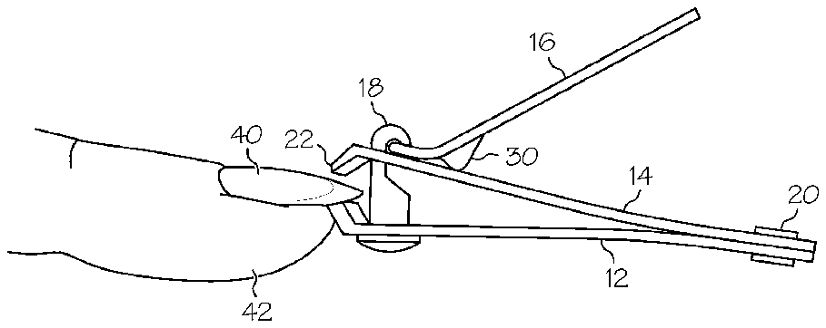
[0004] For some persons, the trimming of fingernails and toenails may pose a particular challenge. For example, young children, elderly people with poor eyesight, or those with other disabilities may find it difficult or impossible to trim their own nails. When a person clips the nails of another person, the person performing the clipping cannot feel whether the clipper is properly positioned to correctly and safely trim the nail.
[0005] Conventional nail clippers include sharp upper and lower blades. In U.S. Pat. No. 1,702,137, Schnefel discloses an example of a conventional nail clipper featuring sharp upper and lower blades. When people use these conventional nail clippers, especially when trimming the nails of another person, they often unintentionally clip the flesh underneath the nail with the sharp bottom blade of the clippers, thereby causing injury.
[0006] As can be understood, there is a need for an apparatus and method for safely trimming the nails of young children and infants, and of other persons for whom trimming of fingernails and toenails may be a challenge.
SUMMARY OF THE INVENTION
[0007] In view of the limitations and disadvantages inherent to conventional means of trimming nails, it is an object of the present invention to provide an apparatus and method for trimming nails that reduces the risk of injury.
[0008] According to one aspect of the present invention, an apparatus for safely clipping nails (hereinafter “safety clipper”) comprises a blade/base assembly, a lever, and a shaft. The blade/base assembly comprises a blade, incorporating a sharp cutting edge for cutting a nail; a base, incorporating a ledge having a front face for aligning the tool to the nail to be clipped and a top face for supporting the nail as the safety clipper is used; and a rivet designed and configured to mechanically fix said blade to said base. The lever is designed to actuate the apparatus, having a fixed end, an unconstrained end, and a cam feature. The fixed end is mechanically fixed to said blade/base assembly by means of a shaft that incorporates a slot designed to simultaneously capture the fixed end of the lever and to place said blade/base assembly into a spring-loaded condition. The cam feature is designed to compress the blade/base assembly as the unconstrained end of the lever is pressed toward blade/base assembly, thereby causing the sharp cutting edge to clamp down on the nail, capturing the nail between the sharp cutting edge and the ledge, and causing the sharp cutting edge to cut through the nail.
[0009] According to another aspect of the present invention, the top face of the ledge incorporates a groove that is designed and configured to align with the sharp cutting edge of the blade and to enable the sharp cutting edge to cut all the way through the nail.
[0010] These and other objects, features, aspects and advantages of the present invention will become apparent to those with skill in the art from the following figures, descriptions and claims. As will be appreciated by those with skill in the art, the apparatus and method of the present invention may be implemented in a plurality of equivalent embodiments. Such alternative embodiments, and their attendant objects, aspects and advantages, are within the scope of the present invention and, therefore, the examples set forth herein shall not be limiting.
BRIEF DESCRIPTION OF THE DRAWINGS
[0011] The nature of this invention, as well as all its objects, aspects and advantages, will become readily apparent and understood upon reference to the following detailed description when considered in conjunction with the accompanying drawings, in which like reference numerals designate like parts throughout the figures thereof, and wherein:
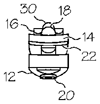
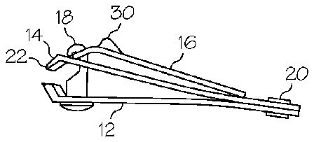
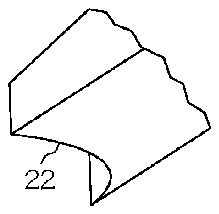
[0012] FIG. 1 presents front, side, top, and perspective detail views of a safety clipper shown in its stowed configuration, according to an exemplary embodiment of the invention;
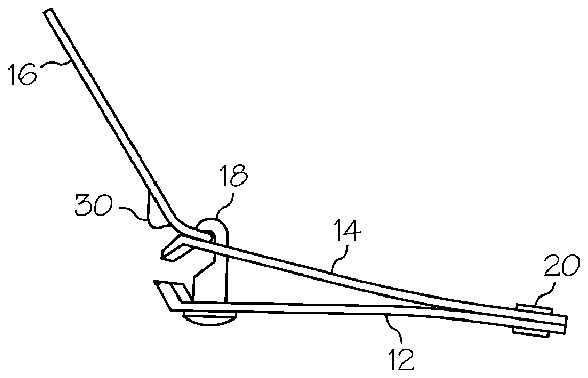
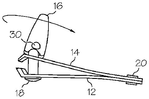
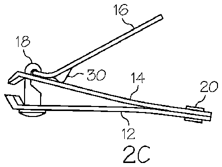
[0013] FIG. 2 illustrates a method of deploying the safety clipper of FIG. 1 , according to an exemplary embodiment of the invention; and
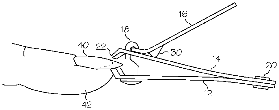
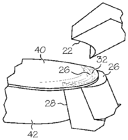
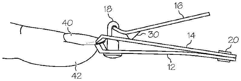
[0014] FIG. 3 illustrates a method of using the safety clipper of FIG. 1 , according to an exemplary embodiment of the invention.
DETAILED DESCRIPTION OF THE INVENTION
[0015] The following description is provided to enable any person skilled in the art to make and use the invention, and sets forth the best modes contemplated by the inventor of carrying out the invention. The present invention shall not be limited to the examples disclosed. Rather, the scope of the invention shall be as broad as the claims will allow.
[0016] Various inventive features are described below that can each be used independently of one another or in combination with other features. However, any single inventive feature may not address any of the disadvantages discussed above, or may only address one of the disadvantages discussed above. Further, one or more of the disadvantages discussed above may not be fully addressed by any of the features described below.
[0017] Broadly, embodiments of the present invention generally provide an improved apparatus for safely trimming the nails of young children and infants, and of other persons for whom trimming of fingernails and toenails may be a challenge. More specifically, the apparatus of the present invention is an improvement over conventional nail clippers. The safety clipper incorporates a ledge feature, in place of the sharp lower cutting blade of conventional clippers, which aligns the safety clipper to the nail to be trimmed and eliminates the possibility of cutting the skin of the finger beneath the nail.
[0018] Referring now to the drawings, FIG. 1 illustrates a safety clipper 10 in its stowed configuration, according to an exemplary embodiment of the invention.
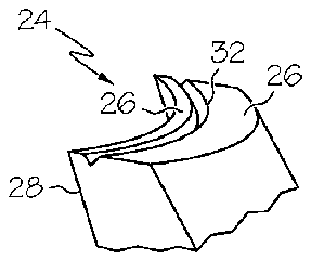
[0019] A front view is presented in FIG. 1A , a side view in FIG. 1B , and a top view in FIG. 1C . A blade 14 may be mechanically fixed to a base 12 by means of a rivet 20 . A lever 16 may be mechanically fixed to this blade 14 /base 12 assembly by means of a shaft 18 which incorporates a slot designed to simultaneously capture the lever 16 and to place the blade 14 /base 12 assembly into a spring-loaded condition. As illustrated in perspective detail view FIG. 1D , the blade 14 may incorporate a sharp cutting edge 22 designed to cut through a nail. The base 12 may incorporate a ledge 24 , having a front face 28 and a top face 26 . A front portion of the ledge 24 may extend outwardly and beyond the sharp cutting edge 22 when the blade is closed against the ledge 24 , as shown in FIGS. 1C and 1D .
[0020] As shown in FIG. 1C , the top view profile of the blade 14 at the sharp cutting edge 22 may be concave in order to conform to the convex shape of a nail. The front face 28 may be a flat or curved surface configured to align the safety clipper 10 to the nail to be trimmed. The top face 26 may comprise a generally flat surface designed to align the safety clipper to the nail to be clipped and to support the nail as the safety clipper 10 is in use.
[0021] FIG. 2 illustrates a method of deploying the safety clipper 10 of FIG. 1 from the stowed configuration to the ready-for-use configuration, according to an exemplary embodiment of the invention. The safety clipper 10 may be deployed in the following manner. First, as illustrated in FIG. 2A , the unconstrained end of the lever 16 may be lifted away from the blade 14 and rotated forward and over the centerline axis of the shaft 18 , the restrained end of the lever 16 thereby compressing the spring-loaded blade 14 /base 12 assembly, until the lever 16 reaches the over-centered position, as illustrated in FIG. 2A . Then, the lever 16 may be rotated 180 degrees about the centerline axis of the shaft 18 , as illustrated in FIG. 2B , until the lever reaches the ready-for-use position, as illustrated in FIG. 2C . The safety clipper 10 may subsequently be reconfigured after use into its stowed, safe configuration by reversing the deployment steps.
[0022] FIG. 3 illustrates a method of using the safety clipper 10 of FIG. 1 , according to an exemplary embodiment of the invention. Starting with the safety clipper 10 in the ready-for-use configuration, as illustrated in FIG. 3A , a user of the safety clipper 10 may align the safety clipper 10 to the nail 40 to be trimmed by placing the top face 26 of the ledge 24 beneath the nail 40 to be trimmed, and pressing the front face 28 of the ledge 24 against the tip of the finger 42 beneath the nail 40 , as illustrated in FIG. 3B . The user of the safety clipper 10 may then press downward on the unconstrained end of the lever 16 , as illustrated in FIG. 3C . As the unconstrained end of the lever 16 is pressed downward toward the blade 14 , a cam feature 30 of the lever may force the sharp cutting edge 22 of the blade 14 to clamp down on the nail 40 , capturing the nail 40 between the sharp cutting edge 22 and the top face 26 of the ledge 24 , as illustrated in FIG. 3C . As the downward force on lever 16 is increased, the sharp cutting edge 22 may cut through the nail 40 , thereby removing the unwanted portion of the nail 40 .
[0023] In one embodiment of the invention, the top face 26 of the ledge 24 may be a generally flat surface.
[0024] In an alternative embodiment of the invention, a groove 32 may be incorporated into the top face 26 of the ledge 24 , as shown in FIGS. 1D , and 3 B. The groove 32 may work in conjunction with the sharp cutting edge 22 to allow the sharp cutting edge 22 to cut all the way through the thickness of the nail 40 , as opposed to pinching the nail 40 . The cross-section of the groove 32 may be in the shape of a “V”, as shown in FIGS. 1D and 3B , or any other useful and practical shape. The groove 32 and the ledge 24 may also provide a visual cue to allow the user to see exactly where the sharp edge 20 will trim the nail. The groove 32 may also be designed as a guide to control the length of nail 40 to be left after clipping by adjusting the distance of the groove 32 from the front face 28 of the ledge 24 .
[0025] The components of the safety clipper may be made of any useful material including, but not limited to metal, wood, plastic or rubber.
[0026] In alternative embodiments of the invention, the top face of the ledge 26 may be a contrasting color to that of skin and nails and/or illuminated such that the user may see that only the nail (and no skin) is resting on the ledge 24 and, therefore, that the nail 40 is ready to safely be trimmed. In further alternative embodiments, the groove 32 may be a contrasting color to that of the ledge 24 or illuminated for increased visibility and accuracy. The ledge 24 may have a rubber surface or overlay to enhance positioning of the safety clipper 10 between the nail and the tip of the finger under the nail.
[0027] In still further alternative embodiments of the invention, the base 12 , the blade 14 and/or the lever 16 may be encased in a material including, but not limited to, plastic, rubber or paint which may act as an outer skin for the purpose of aiding in gripping the safety clipper 10 , or simply for aesthetics.
[0028] It is within the contemplated scope of the invention that the ledge 24 and/or groove 32 features of the present invention may be incorporated into other clipper configurations, both currently known in the art and yet to be designed.
[0029] As can be appreciated by those skilled in the art, embodiments of the present invention provide an improved apparatus for safely trimming the nails of young children and infants, and of other persons for whom trimming of fingernails and toenails may be a challenge.
[0030] It should be understood, of course, that the foregoing relates to exemplary embodiments of the invention, and that modifications may be made without departing from the spirit and scope of the invention as set forth in the following claims. The elements of the device may be modified, interchanged, separated or combined, or additional elements added without departing from the spirit of the invention. The invention may be practiced in alternative embodiments other than those illustrated in the Figures. Such modifications, combinations, additions and alternatives are within the contemplation of the present invention. The exemplary embodiments disclosed are not intended to limit the scope of this invention. Accordingly, the scope of the invention should be determined not by the embodiments illustrated, but by their legal equivalents, and shall be as broad as the claims will allow.

