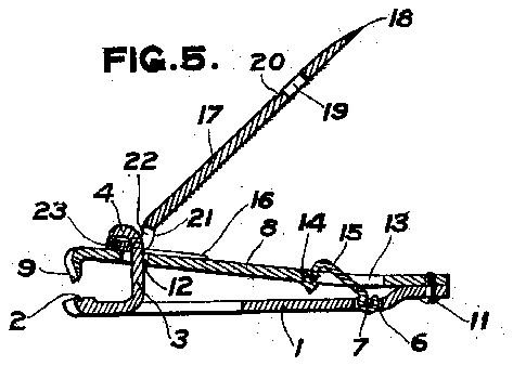
- 1member
- 2seat
- 3hook
- 4hook
- 5per- 'foration
- 6opening
- 7bar
- 10foration
- 11a screwrivet or other suitable fastening
- 12perforation
- 14tongue
- 15hook
- 16its upper surface two longitudinal ribs
- 17lever
- 18point
- 19opening
- 21u-shaped portion
- 22perforation
- 23portion
Description
l PATBNTED MAR. 12, 1907. G. HAVELL. NAIL GLIBPER, AIPLIGATION FILED .JA-N. 29, 19.06.
Flc..
FIG.2.
WITNEssEs f INvEN-ron:
1HE NoRRrs PETER: co., wasnmarcm. n. c.
UNITED STATES RTENT oEEioE.
GEORGE EAVELL, or NEWARK, NEW JERSEY, ASSTGNOR To LOUIS o. LANGIE,
- OE ROCHESTER, NEW YORK.
NAIL-CLIPPER.
Specification of Letters Patent.
Patented March 12, 1907.
Application filed January 29,1906. Serial No. 298.335.
T0 /LZZ whom, t may concern.-
-Be it known that l, GEORGE HAvELL, a citizen of the United States, and a resident of Newark, in the county of Essex and State `of New Jersey, have invented certain new and useful Improvements in Nail-Clippers, of which the following is a specification.
This invention relates to nail-clippers, and consists inthe mechanism and arrangement of parts hereinafter described and claimed.
The object of the invention is to provide a compact and durable nail-clipper, the parts of which are easy to manufacture and assemble.
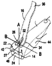
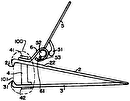
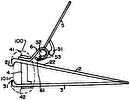
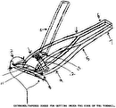
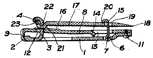
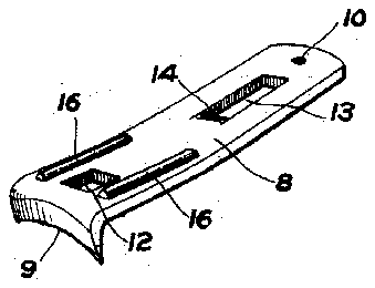
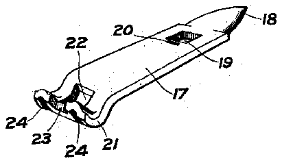
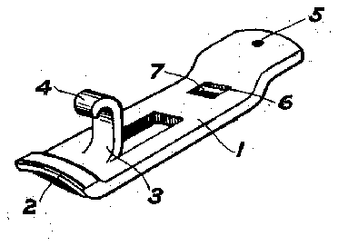
In the drawings, Figure 1 is a vertical medial section through a nail-clipper embodying this invention. Figs. 2, 3, and 4 are perspective views of parts of the nail-clipper; and Fig. 5 is avertical medial section through a nail clipper embodying this invention, showing the parts in the open position ready to be operated for clipping purposes.
This nail-clipper is composed of two jaws, movable toward and from each other by means of a lever. The said jaws are fastened rigidly together at one end and at the other are formed into a cutter, which in the present instance consists of a cutting-blade acting against a seat. l
One of the cutting-jaws 1 has upon it a curved seat 2 and is provided with an integral bearing-plate 3, which in the present case terminates in a hook 4. The bearing plate and hook are formed, as clearly shown in Fig. 4, from a tongue which is punched from the body of the jaw 1 The end of the jaw or member 1` opposite the end having the seat 2 is preferably bent out of the plane of the main portion of the body and is perfo# rated, as at 5, near that end, for apurpose to be described. The said member 1 is also perforated, as at 6, leaving in the center of the perforation a bar 7, which may be rounded. f
The other member or jaw 8 (shown most clearly in Fig. 3) is formed of a material which can be tempered, and has at one end a downwardly-turned sharp edge 9, adapted to cooperate with the seat 2 in the jawor member 1. foration 10, adapted to register with the per- 'foration 5 in the other member, anda screwrivet or other suitable fastening 11 passes The jaw 8 at its other end has a per-l other perforations, one of which, 12, is f adapted to permit the passage of the tongue and hook 3 and-4, and the other perforation 13 has a downwardly-turned tongue 14, for purposes hereinafter to be` described. To the transverse bar 7 in the Opening 6 in the member or jaw 1 is attached a swinging hook 15, which projects upward through the per foration 13 in the jaw or member 8. The tongue 14 is in such a position and is at such an angle to the body ofthe member 8 that in the movement of the jaw 8 with reference to the jaw 1 the hook 15 will slide along the surface of the tongue 14 without engaging it. The tongue 14 also when the parts are closed, as shown in Fig. 1, for cutting purposes may bear against the member 1.
The member has on its upper surface two longitudinal ribs 16, preferably near the side edges of the member and on opposite sides of the perforation 12.
The two members or cutting-jaws above described are operated by means of a lever 17, (shown most clearly in Fig. 2,) which at its free end is provided with a point 18 suitable kfor use as a nail-cleaner. Adjacent to the free end is an opening 19, through which the hook 15 passes when the parts are in the closed position shown in Fig. 1, and on the upper surface of the lever 1,7 and adjacent to the edge of the perforation .19 may be a socket 20, into which the edge of said hook 15 may set, as shown in Fig. 1, for the more certain securing of the parts in position. The other end of the lever 17 is bent downward into the U-shaped portion 21 and has a perforation 22 for the passage of the tongue and hook 3 and 4, so that a cross bar or part 23, at or near the extremity of the lever 17 and on one side of the Ushaped portion 21,
may engage under the hook 4 of the tongue IOO tension of the two jaws causes the portion 23 to press close upon the upper face of the member 8, and thus leaves the free `end of the lever 17 away from the remainder of the clipper, as shown in Fig. 5. If now the nail is inserted between the cutting-jaws 9 and 2 and the free end of the lever 17 is depressed, the cutting-jaws will be brought together with great force, because the fulcrum of the lever 17 (at the U-shaped portion 21) presses against and slides along the member S, and
the cutting operation will be produced with great force. On releasing the lever 17 the parts will open to the position shown in Fig. 5. When the device is to be carried in a pocket, the hook 15 is so tilted that when the lever 17 is brought to the position shown in Fig. 1 the said hook will pass through the opening 19, when it may be caused to engage said lever. If the edge of the hook 15 is set in the notch 20, the spring-pressure of the parts will hold the hook in position and retain the nail-clipper with the parts in the position shown in Fig. 1.
l/Vhat l claim is-A 1, A nail-trimmer comprising plates fastened together at one end, one of which is of resilient material, and having jaws at their other ends, one of said plates being perforated adjacent to its jaw, and the other having a hook adapted to pass through the perforation in the other plate, a lever adapted to .engage said hook above the perforated plate and to close the jaws, and means for preventing lateral movement of the lever.
2. A nail-trimmer comprising plates fastened together at one end, one of which is of resilient material, and having aws at their other ends, one of said plates being perforated adjacent to its aw, and the other having a hook adapted to pass through the perforation in the other plate, a lever adapted to enw gage said hook above the perforated plate and to close the aws, and a hook pivoted to the lower plate and extending up through registering apertures in the other plate and the operating-lever respectively the aperture in said other plate being elongated as shown to permit the pivoted hook to swing forwardly therein out of the way of the lever.
3. A nail-trimmer comprising plates fastened together at one end, one of which is of resilient material, and having j aws at their other ends, one of said plates being perforated adjacent to its jaw, and the other having a hook adapted to pass through the perforation in the other plate, a lever adapted to engage said hook above the perforated plate and to close the jaws, and engaging guide means on the lever and said perforated plate for preventing lateral movement of the lever.
1. A nail-trimmer comprising plates of resilient material fastened together at one end, and having jaws at their other ends that normally tend to open, a lever pivotally supported by one of said plates above the other,
adapted to close the jaws when folded down upon the upper plate, and having a -perforation in its free end, and a hook pivoted to the under plate, extending up through a perforation in the upper plate, and adapted to pass through the perforation in said lever to engage and lock said lever down upon the upper plate g said perforation being elongated to permit the hook to swing forwardly out of the way of the downward movement of said lever.
5. A nail-trimmer comprising plates of resilient material fastened together at one end, and having jaws at their other ends that normally tend to open, one of said plates being perforated and having a stop at the edge of said perforation to limit the movement of said jaws, a lever pivotally supported above the perforated plate by the other plate and adapted to close the jaws when folded down upon the upper plate, and a hook pivoted upon the lower plate, adapted to extend through the perforation in the upper plate to engage and loch the lever down upon the upper plate, and, when disengaged from said lever, to lie below the surface of said upper plate, against said stop.
6. A nail-trimmer comprising spring-controlled jaws tending normally to open, a bearing-plate carrying one of said jaws, and having a bearing at its free end, a lever having a transverse bar in said bearing, and adapted to close said aws, and engaging guide means on said lever and the adjacent jaw for preventing lateral movement of said lever.
7. A nail-trimmer comprising spring-con trolled jaws tending normally to open, a bearing-plate carrying one of said jaws, and having a bearing at its free end, a lever having a transverse bar in said bearing', and adapted to close said jaws, and engaging means on said lever and the adjacent jaw, consisting of a rib on one of said parts and a groove on the other, for preventing lateral movement of the lever.
. 8. A nail-trimmer comprising spring-controlled jaws tending normally to open, one of said jaws having one or more longitudinal ribs upon its outer surface, and a lever pivotally supported above the jaw last mentioned, having a shoulder adapted to engage said jaw and to depress it, and grooves insaid shoulder to receive said ribs.
GEORGE HAVELL.
Wlitnesses:
JAMES D.' CLARK, EMIL LEIBE.
ICO

